Device and method for aligning an eye with a surgical laser

a laser and eye technology, applied in laser surgery, medical science, diagnostics, etc., can solve the problems of reducing the efficacy of laser surgery, affecting the accuracy of laser surgery, and inability to correct involuntary eye movements by instruction, etc., to achieve accurate delivery

Active Publication Date: 2008-06-24
TECHNOLAS PERFECT VISION
View PDF22 Cites 120 Cited by
  • Summary
  • Abstract
  • Description
  • Claims
  • Application Information

AI Technical Summary

Benefits of technology

[0010]The present invention is directed to a device for establishing a desired contact alignment between a patient's eye and a laser system. Once properly aligned, the eye can be safely engaged with the laser system to hold the eye stationary relative to the laser system. This fixed arrangement then allows a surgical beam to be accurately delivered from a source and focused to a selected ocular location.
[0011]As intended for the device of the present invention, a platform is provided for supporting the patient during a surgical procedure. Further, the platform is moveable relative to a laser system. Typically, the platform is configured for independent movement along each of three mutually orthogonal axes (e.g. x, y and z axes), and is moveable in response to a control signal from a system controller. In an alternate arrangement for the device of the present invention, the laser system can be mounted on the moveable platform, and the combination of platform and laser system can be reconfigured to control movement of the laser system relative to the patient's eye.

Problems solved by technology

Unfortunately, movements of the eye relative to the laser source can undermine the accuracy of the laser and reduce the efficacy of the laser procedure.
On the other hand, involuntary eye movements cannot be remedied by instruction, and as a consequence, they must be somehow controlled.
Unfortunately, these eye tracking systems tend to be overly complicated, and, as a practical matter, do not always provide the reliability that is required for certain types of procedures.
For example, for procedures wherein the laser is configured to ablate and destroy selected tissue, an error or malfunction of the tracking system can result in the immediate destruction of non-target tissue.
For obvious reasons, large pressures applied to the eye are often uncomfortable to the patient and can result in post-operative pain and scarring.
Moreover, the pressure can cause damage to the eye by increasing the intra-ocular pressure of the eye to dangerous levels.
In these procedures, movements of the eye must be accommodated and corrected for and this often results in a relatively slow, labor intensive procedure, the satisfactory performance of which is highly dependent on the skill and patience of the surgeon.

Method used


Image

  • Device and method for aligning an eye with a surgical laser
  • Device and method for aligning an eye with a surgical laser
  • Device and method for aligning an eye with a surgical laser

Examples


Embodiment Construction

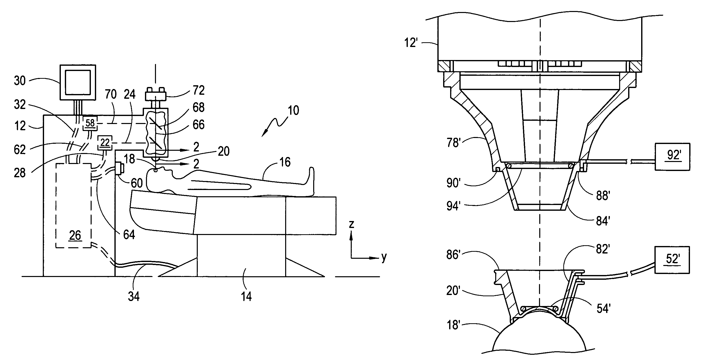
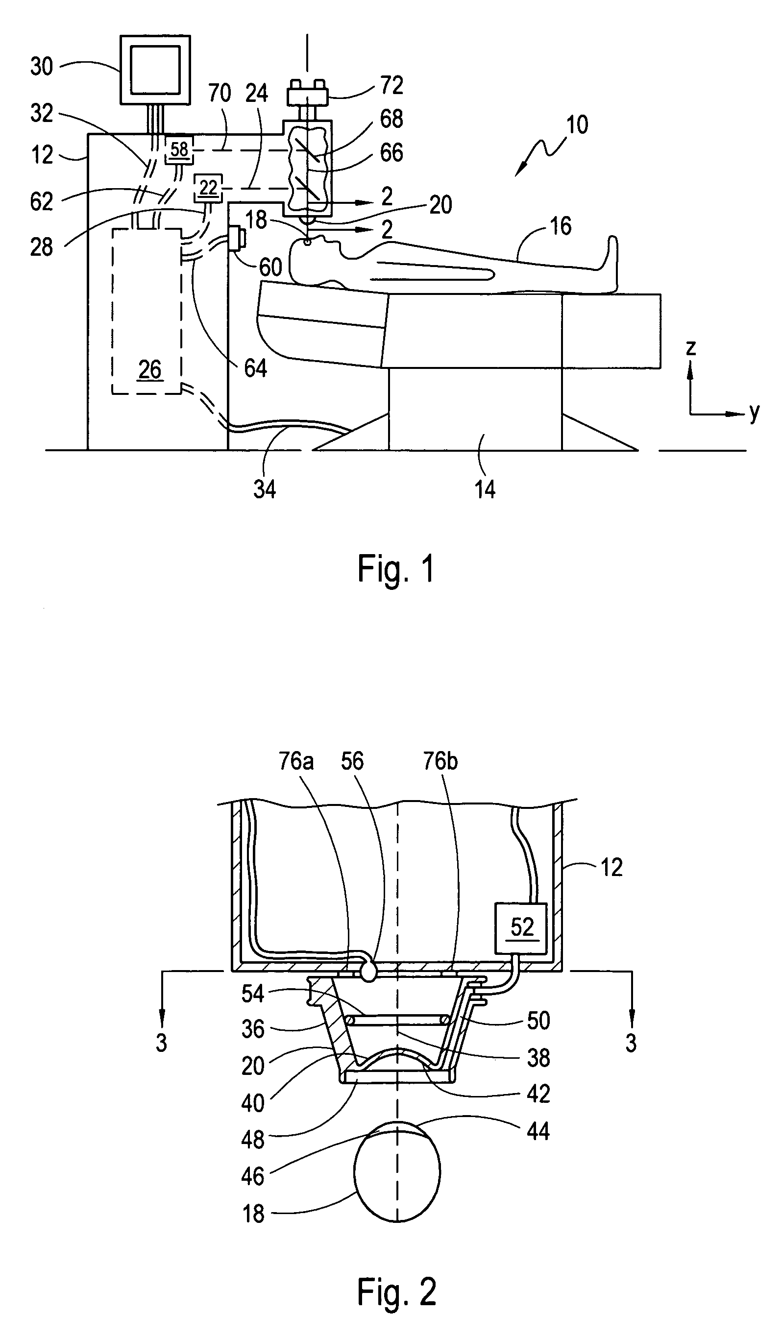
[0023]An apparatus for performing an ocular laser procedure is shown in FIG. 1 and is generally designated 10. As shown, the apparatus 10 includes a stationary surgical laser system 12 and a platform 14, which for the embodiment shown is a motorized chair. For the apparatus 10, the platform 14 is configured to support a patient 16, and is moveable to align the eye 18 of the patient 16 with an eye stabilizing element 20 which is rigidly attached to the laser system 12. On the other hand, the laser system 12 can be moved relative to the platform 14 to accomplish this same purpose. Once aligned, the platform 14 can be moved to engage the eye 18 with the eye stabilizing element 20.

[0024]For the apparatus 10, the laser system 12 also includes a laser source 22 for generating a laser beam and directing the beam along beam path 24, as shown. Laser source 22 is activated and controlled by a system controller 26 via cable 28. For the apparatus 10, the system controller 26 typically includes ...


PUM


Abstract

A device for establishing a desired alignment between a patient's eye and a laser system to facilitate an engagement therebetween includes a light source to illuminate the eye. A moveable platform is provided to move the patient relative to the laser system. To establish alignment between the eye and the laser system, a reference marker is based on the laser system. An image of the marker, along with reflections from the illuminated eye, is then transmitted to the system controller. There, the image and reflections are processed to determine a measured alignment that is then compared to the desired alignment. An error signal that is indicative of an alignment difference is then generated and used to incrementally move the platform, or the patient, in an appropriate direction.

Description

FIELD OF THE INVENTION[0001]The present invention pertains generally to devices and methods for performing ocular laser surgery. More particularly, the present invention pertains to devices for positioning the eye of a patient for laser surgery. The present invention is particularly, but not exclusively, useful as a device for establishing a contact alignment between a patient's eye and a laser system to facilitate the engagement of the eye with the laser system prior to a refractive laser surgery procedure.BACKGROUND OF THE INVENTION[0002]Surgical lasers are now commonly used in a variety of ophthalmic applications, including the diagnosis and treatment of ocular diseases, as well as the diagnosis and correction of optical deficiencies. As an example, corneal reshaping procedures using lasers, such as the well known LASIK procedure, are now widely available. In all of these procedures, the surgical laser is chosen as the tool of choice because of the ability of the laser to be accu...

Claims


Application Information

Patent Timeline
Patent Type & Authority Patents(United States)
IPC IPC(8): A61B3/00
CPCA61F9/008A61F9/009A61B2017/306
Inventor LOESEL, FRIEDERMEISEL, FRITZGRESS, BERNHARDKUHN, TOBIAS
Owner TECHNOLAS PERFECT VISION
Why Eureka
Try Eureka