Loss minimized PWM for voltage source inverters taking into account inverter non-linearity

a voltage source inverter and non-linearity technology, applied in the field of pulse width modulation, can solve the problem of low inverter losses

Active Publication Date: 2008-06-24
GM GLOBAL TECH OPERATIONS LLC +1
View PDF3 Cites 33 Cited by
  • Summary
  • Abstract
  • Description
  • Claims
  • Application Information

AI Technical Summary

Problems solved by technology

Typically, DPWM control methods result in lower inverter losses than continuous PWM control methods.

Method used


Image

  • Loss minimized PWM for voltage source inverters taking into account inverter non-linearity
  • Loss minimized PWM for voltage source inverters taking into account inverter non-linearity
  • Loss minimized PWM for voltage source inverters taking into account inverter non-linearity

Examples


Embodiment Construction

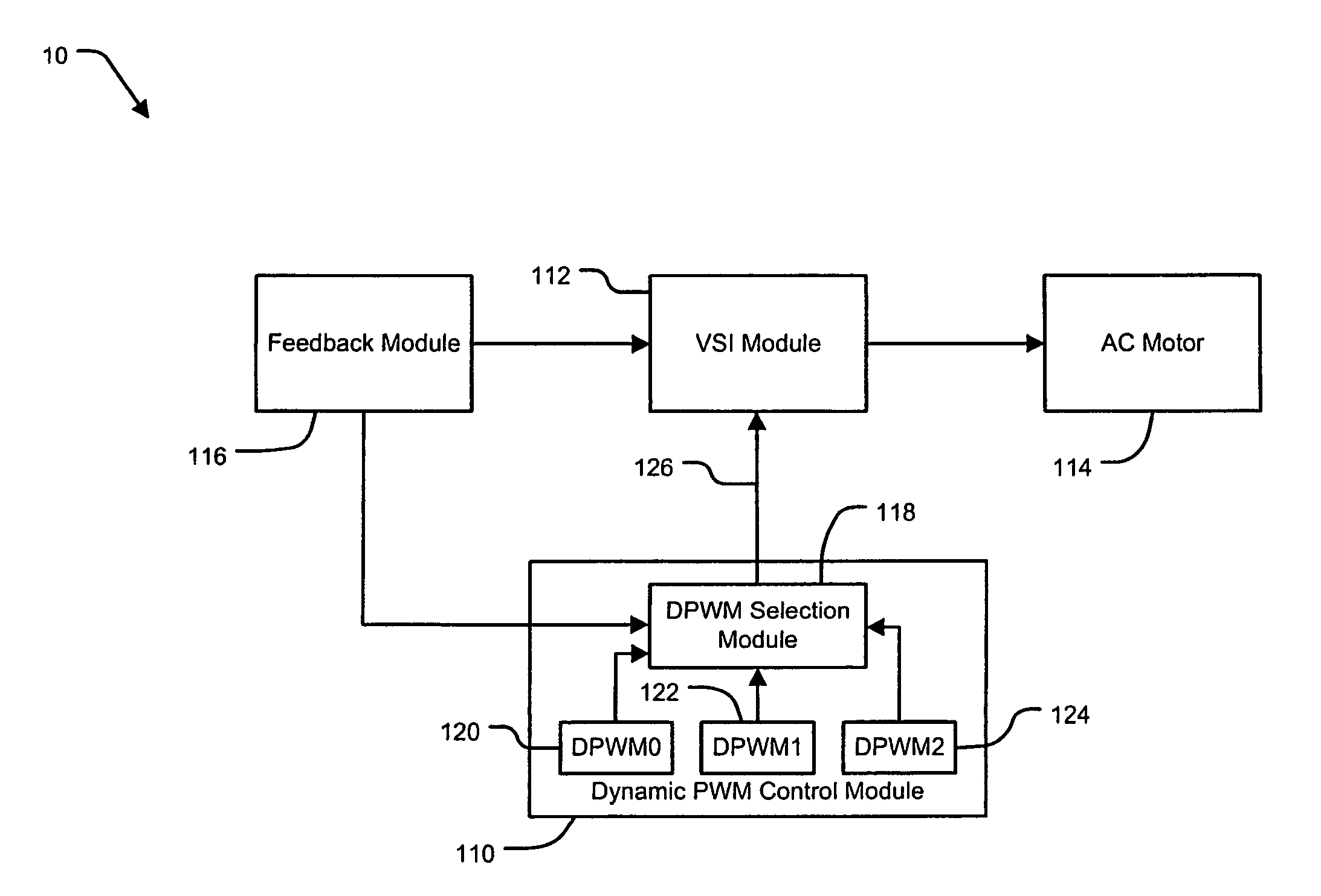
[0024]The following description of the preferred embodiment(s) is merely exemplary in nature and is in no way intended to limit the invention, its application, or uses. For purposes of clarity, the same reference numbers-will be used in the drawings to identify similar elements. As used herein, the term module and / or device refers to an application specific integrated circuit (ASIC), an electronic circuit, a processor (shared, dedicated, or group) and memory that execute one or more software or firmware programs, a combinational logic circuit, and / or other suitable components that provide the described functionality.

[0025]As described above, each of the DPWM control methods DPWM0, DPWM1, and DPWM2 are optimized for particular control operations. However, the nonlinear relationship between a voltage source inverter (VSI) and an AC motor demonstrates practical control limitations of the DPWM control methods. For example, a selected DPWM control method may be unable to accurately contr...


PUM


Abstract

A dynamic pulse width modulation (PWM) selection device automatically switches between discontinuous PWM (DPWM) control methods. The PWM selection device comprises a PWM control module. The PWM control module determines a desired pulse width of a switching control signal according to a desired output signal. The PWM control module controls an actual pulse width of the switching control signal according to the desired pulse width and a first PWM control method. A selection module determines whether the desired pulse width exceeds a pulse width threshold. The selection module selects a second PWM control method when the desired pulse width exceeds the pulse width threshold.

Description

FIELD OF THE INVENTION[0001]The present invention relates to pulse width modulation, and more particularly to selecting between pulse width modulation methods to minimize inverter losses.BACKGROUND OF THE INVENTION[0002]A voltage source inverter (VSI) is used to generate an AC output voltage with controllable magnitude and frequency. The VSI converts a DC voltage to the AC voltage in order to drive a three phase AC motor. Pulse width modulation (PWM) methods are used to control the operation of the VSI. A PWM control module provides high-frequency voltage pulses that control a duty cycle of one or more switches in the VSI.[0003]Referring now to FIG. 1, an exemplary three-phase VSI 10 that drives an AC motor 12 is shown. The VSI 10 includes one or more DC voltage sources 14 and 16 and switches 18-1, 18-2, 20-1, 20-2, 22-1, and 22-2, referred to collectively as switches 24. The switches 24 are any suitable semiconductor switches as are known in the art, such as transistors including a...

Claims


Application Information

Patent Timeline
Patent Type & Authority Patents(United States)
IPC IPC(8): H02P23/00
CPCH02P27/04H02M2001/0048Y02B70/1491H02M1/0048Y02B70/10
Inventor WELCHKO, BRIANSCHULZ, STEVEN E.HITI, SILVA
Owner GM GLOBAL TECH OPERATIONS LLC
Why Eureka
Try Eureka