Circuit and method for pulse width modulation

a pulse width modulation and circuit technology, applied in pulse modulation, pulse technique, electrical apparatus, etc., can solve problems such as the worsening of the emi phenomenon, achieve the effects of improving the emi phenomenon, improving the pwm audio quality, and reducing the operating clock frequency

Inactive Publication Date: 2008-06-24
SUNPLUS TECH CO LTD
View PDF3 Cites 47 Cited by
  • Summary
  • Abstract
  • Description
  • Claims
  • Application Information

AI Technical Summary

Benefits of technology

[0008]Therefore, the present invention is directed to a circuit and a method of performing pulse width modulation. The circuit and method according to an embodiment of the present invention, are capable of improving the audio quality of pulse width modulation without having to increase the operating clock frequency; capable of reducing the operating clock frequency under the condition of providing the same PWM audio quality so as to improve the EMI phenomenon; and capable of providing more choices of sampling rate under the condition of providing the same audio quality and the same operating clock frequency.
[0017]In summary, the present invention has at least the following advantages.
[0018]1. In the present invention, the dithering PWM signal is generated by only feeding the most M bits of the M+N bits input data into the pulse width modulator, and by only feeding the least N bits of the input data into the PDM. Therefore, compared with the conventional M bits pulse width modulator, the present invention can improve the PWM audio quality without having to increase the operating clock frequency.
[0019]2. Under the condition of providing the same PWM audio quality, for example, if the input data is I bits, only the most I-N bits of the input data is fed into the pulse width modulator, and the least N bits of the input data is fed into the PDM to generate the dithering PWM data. Since fewer bits are fed into the pulse width modulator, the operating clock frequency is reduced and the EMI phenomenon is improved.
[0020]For example: assuming the operating frequency for a 10 bits pulse width modulator is 24 MHz, thus its frame frequency is 48 KHz (24 MHz / 2^9). With such method, under the condition of N=2 and the same 10 bits audio quality and frame frequency, its operating frequency is only 6 MHz, since the frame frequency for a physically used 8 bits pulse width modulator is 48 KHz. The 6 MHz operating frequency effectively reduces its operating frequency and improves the EMI phenomenon.
[0021]3. Since fewer bits are fed into the pulse width modulator, the maximum pulse width required by the pulse width modulator is also reduced. Therefore, under the condition of providing the same operating clock frequency, the present invention provides more choices of sampling rate.

Problems solved by technology

As a result, the EMI phenomenon is getting worse in such case.

Method used


Image

  • Circuit and method for pulse width modulation
  • Circuit and method for pulse width modulation
  • Circuit and method for pulse width modulation

Examples


Embodiment Construction

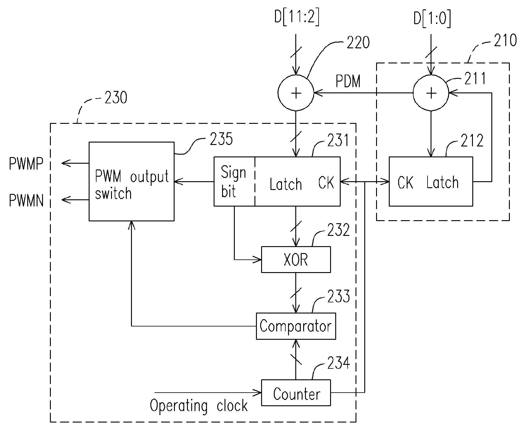
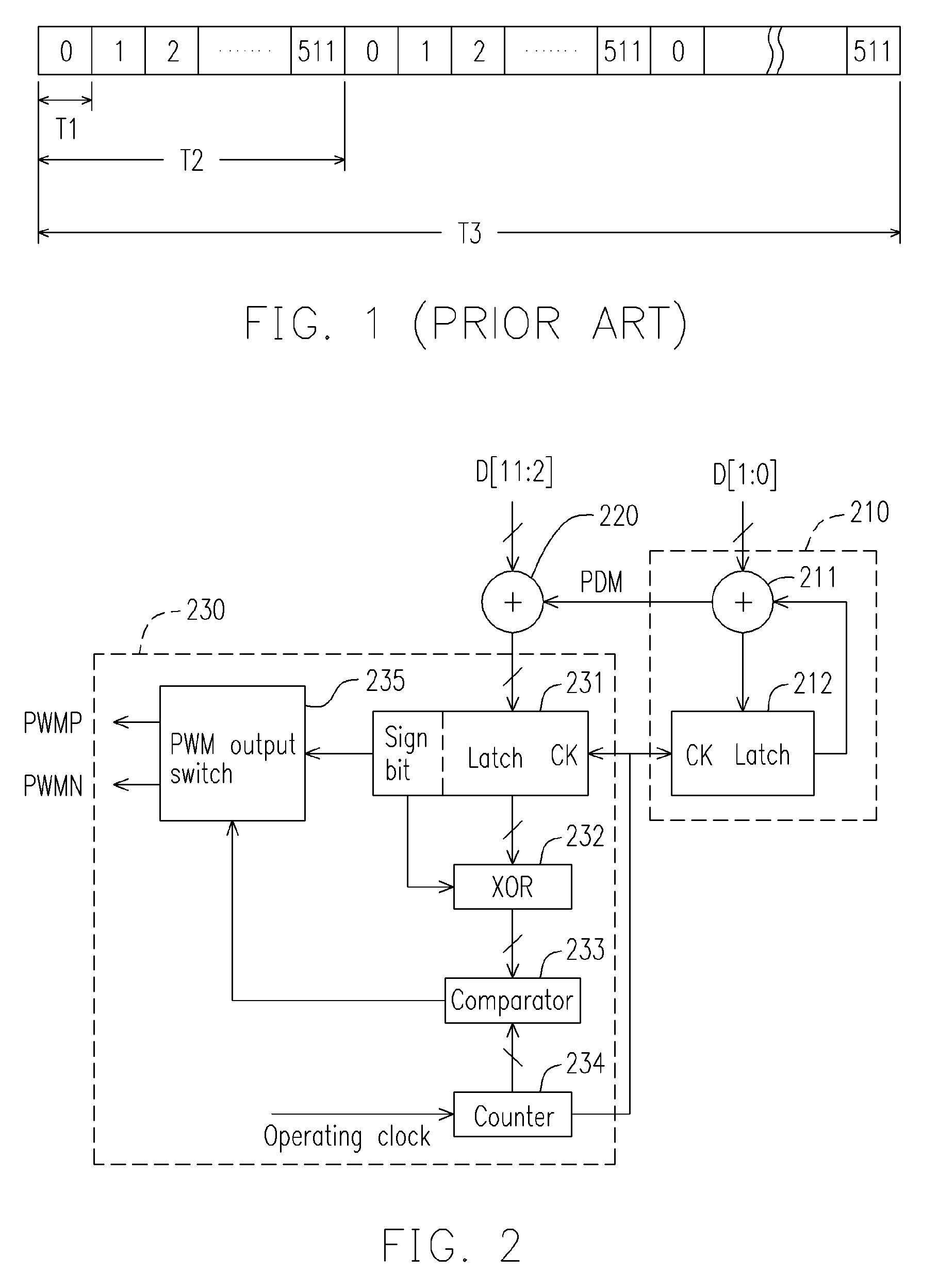
[0027]FIG. 2 is a schematic block diagram of a PWM circuit according to a preferred embodiment of the present invention. The pulse width modulator is suitable for generating a PWM signal according to an input data with M+N bits. The pulse width of the PWM signal dither in 2^N frames and correspond to the value of the input data. Wherein, since the input data D[M:N] has a signed value, i.e. the D[M] bit is a signed bit, the generated PWM signal comprises a positive PWM signal PWMP and a negative PWM signal PWMN.

[0028]In FIG. 2, in the case of M=10, N=2, if the input data D[11:0] is “00,1000,0000,01”, i.e. if the pulse width of the positive PWM signal PWMP to be transmitted is 128.25 operating clock cycles, a positive PWM signal PWMP with 128 operating clock cycles are transmitted in each of the 1st˜3rd frame, and a positive PWM signal PWMP with 129 operating clock cycles are transmitted in the 4th frame. Accordingly, the average pulse width of the positive PWM signal PWMP is 128.25 o...


PUM


Abstract

A circuit and a method for performing pulse width modulation are provided. A pulse density modulator (PDM) is applied to receive the least N bits of the input data and to generate a pulse density modulation signal. The number of pulse of the pulse density modulation signal in 2^N frames correspond to a value of the least N bits of the input data. An adder is applied to generate a PWM data by adding a value of the most M bits of the input data to a value of the pulse density modulation signal generated by the PDM. A pulse width modulator is applied to generate a PWM signal dithering in 2^N frames according to the PWM data generated by the adder, so as to improve the audio quality of pulse width modulation and the Electro-Magnetic Interference (EMI) phenomenon.

Description

CROSS REFERENCE TO RELATED APPLICATIONS[0001]This application claims the priority benefit of Taiwan application serial no. 93103702, filed Feb. 17, 2004.BACKGROUND OF INVENTION[0002]1. Field of the Invention[0003]The present invention relates to a circuit and a method for performing pulse width modulation, and more particularly, to a circuit and a method for performing pulse width modulation capable of improving the audio quality of pulse width modulation and the Electro-Magnetic Interference (EMI) phenomenon.[0004]2. Description of Related Art[0005]Pulse width modulation (PWM) is a modulation technique most commonly used in the digital circuit for processing audio signals. The so-called PWM technique adjusts a pulse width of the output audio signal by referring to an operating clock cycle that represents a PWM service rate and according to a value of the digitized audio data when generating the audio signal.[0006]FIG. 1 is a schematic diagram of performing pulse width modulation on...

Claims


Application Information

Patent Timeline
Patent Type & Authority Patents(United States)
IPC IPC(8): H03K7/08
CPCH03K7/08
Inventor HSU, HAM-HUAH
Owner SUNPLUS TECH CO LTD
Why Eureka
Try Eureka