Memory module assembly including a clamp for mounting heat sinks thereon

a memory module and heat sink technology, applied in the direction of insulated conductors, cables, lighting and heating apparatus, etc., can solve the problem of mounting heat sinks to the memory module assembly,

Inactive Publication Date: 2008-06-24
HON HAI PRECISION IND CO LTD +1
View PDF12 Cites 57 Cited by
  • Summary
  • Abstract
  • Description
  • Claims
  • Application Information

AI Technical Summary

Problems solved by technology

However, since the memory module assemblies each have a limited board area and are mounted on a motherboard of a computer, mounting the heat sink to the memory module assembly becomes an issue.

Method used


Image

  • Memory module assembly including a clamp for mounting heat sinks thereon
  • Memory module assembly including a clamp for mounting heat sinks thereon
  • Memory module assembly including a clamp for mounting heat sinks thereon

Examples


Embodiment Construction

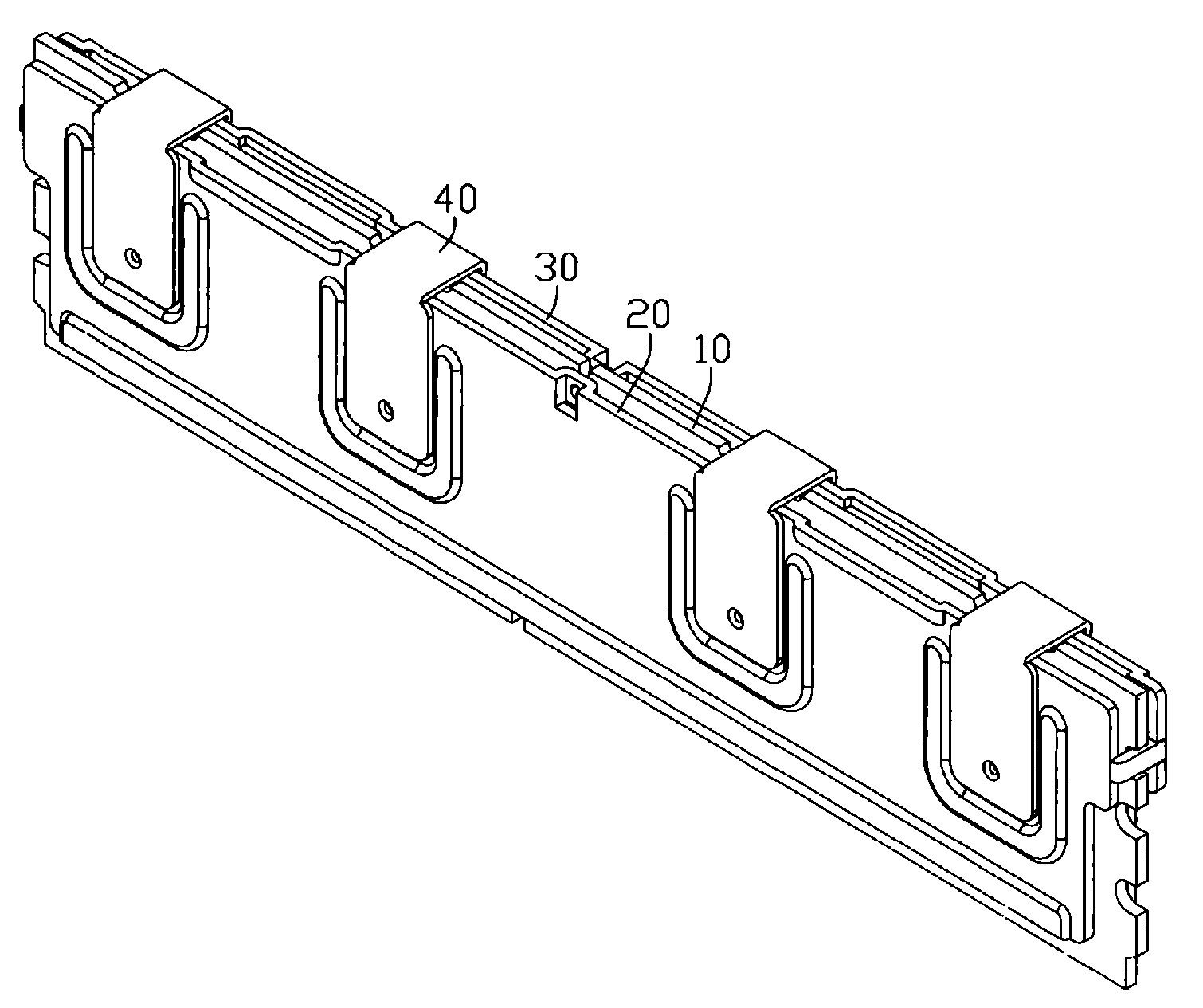
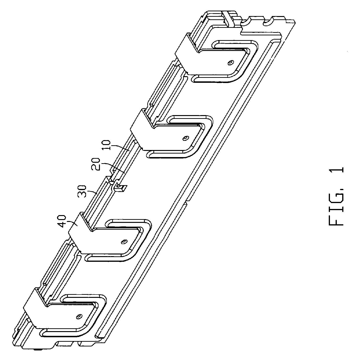
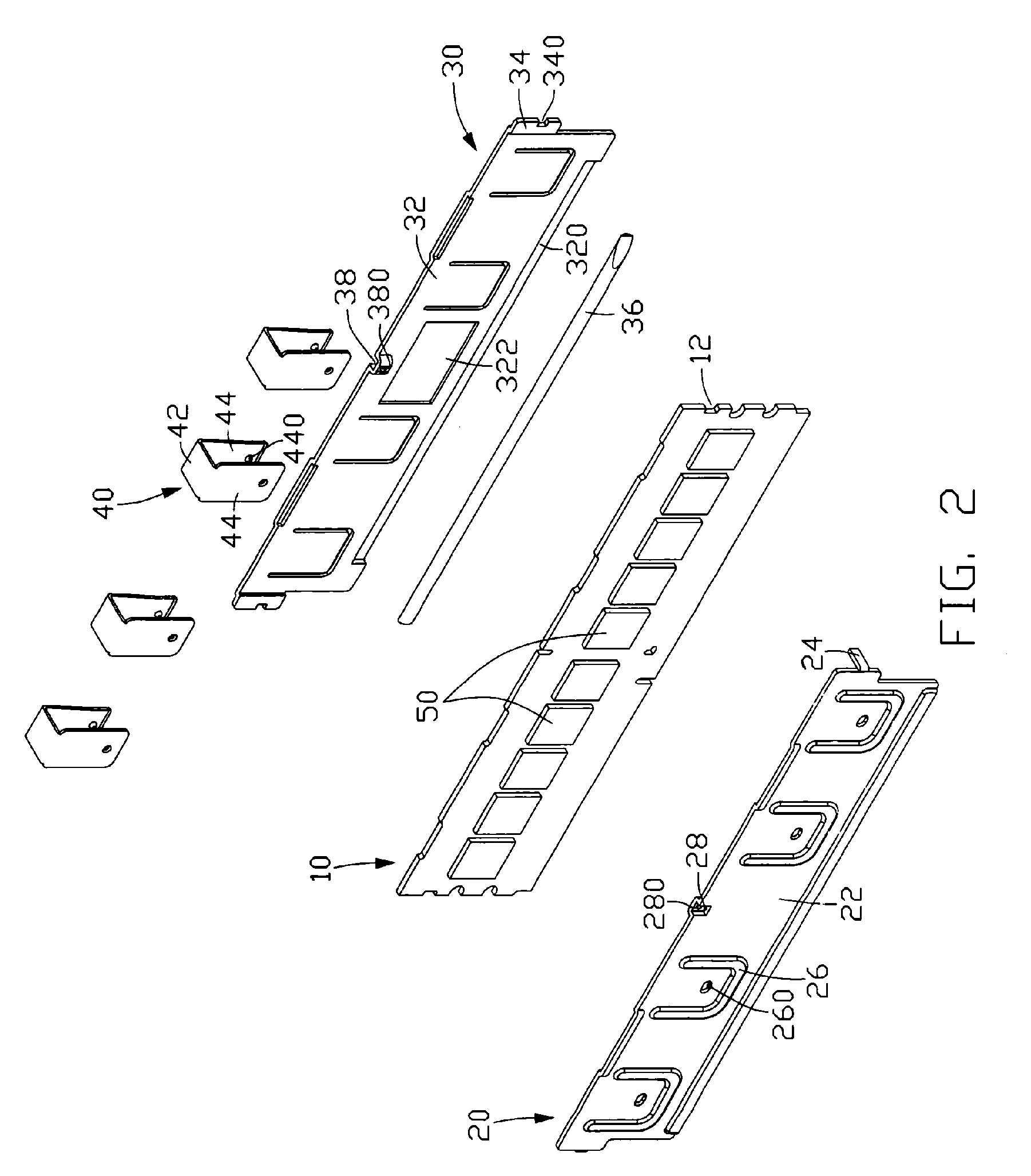
[0010]FIGS. 1-2 show a memory module assembly in accordance with a preferred embodiment of the present invention. The memory module assembly comprises a printed circuit board 10 having a plurality of heat-generating electronic components 50 thereon, a first heat sink 20, a second heat sink 30 and four clamps 40 for securing the first and second heat sinks 20, 30 onto opposite sides of the printed circuit board 10. The printed circuit board 10 has a rectangular shape having first and second faces and two long sides and two short sides between the long sides. A pair of openings 12 is defined in edges of the opposite short sides of the printed circuit board 10. The printed circuit board 10 further comprises a main heat-generating electronic component 52 (referring to FIG. 4) producing more heat than any one of the heat-generating electronic components 50. The main heat-generating electronic component 52 is arranged facing the second heat sink 30 and located at a middle of a rear surfac...


PUM


Abstract

A memory module assembly includes a printed circuit board (10) having a main heat-generating electronic component (52) thereon, first and second heat sinks (20), (30) attached on opposite sides of the printed circuit board and a clamp (40) clamping the first, second heat sinks and the printed circuit board together. The first heat sink comprises a pair of positioning poles (24). The second heat sink comprises a heat pipe (36) disposed therein and thermally connecting therewith. The clamp comprises a connecting portion (42) and a pair of elastic pressing portions (44). The clamp resiliently presses the second heat sink toward the main heat-generating electronic component and the first heat sink engages with the second heat sink via the positioning poles of the first heat sink extending in and engaging with the second heat sink.

Description

FIELD OF THE INVENTION[0001]The present invention relates generally to memory module assemblies, and more particularly to a memory module assembly including a clamp for mounting a heat sink to an electronic component attached on a surface of a printed circuit board of the memory module assembly.DESCRIPTION OF RELATED ART[0002]Memory module assemblies that are currently in use generally do not require cooling devices to dissipate heat. The electronic components and memory module assemblies currently available, which are operated on or below 66 MHz do not generate heat that requires a cooling device for dissipating the heat. However, as the industry progresses, memory module assemblies, such SDRAM DIMM memory module assemblies are required to be operated at 100 MHz or more. For these modern memory module assemblies, heat sinks will be required to remove heat generated thereby. However, since the memory module assemblies each have a limited board area and are mounted on a motherboard o...

Claims


Application Information

Patent Timeline
Patent Type & Authority Patents(United States)
IPC IPC(8): H05K7/20
CPCH01L23/3672H01L23/4093H01L2924/0002H01L2924/00
Inventor LAI, CHENG-TIENZHOU, ZHI-YONGDING, QIAO-LI
Owner HON HAI PRECISION IND CO LTD
Why Eureka
Try Eureka