Image forming apparatus

a technology of forming apparatus and forming tube, which is applied in the direction of printing, etc., can solve the problems of inability to obtain a sufficient suction force, increase in ink consumption, and image degrade,

Inactive Publication Date: 2008-07-01
RICOH KK
View PDF4 Cites 7 Cited by
  • Summary
  • Abstract
  • Description
  • Claims
  • Application Information

AI Technical Summary

Benefits of technology

[0009]The present disclosure provides an image forming apparatus whereby a foreign body such as dust can be prevented from coming into a suction cap so that a sufficient suction force is maintained for a long period of time.
[0024]According to the above-mentioned gradation reproducing method, the suction cap configured to maintain the jet opening is provided separately from the moisture retention cap having the suction part configured to suction the ink situated at the jet opening part. Under this structure, ink is prevented from being adhered on an internal wall surface of the moisture retention cap and therefore viscosity of the ink is prevented from being increased at the time of maintaining moisture at the jet opening. The shutter member is provided so as to come in contact with the perimeter of the edge part forming the opening part of the suction cap in a case where the shutter member is closed. Under this structure, a foreign body such as dust is prevented from entering the suction cap and the dust is prevented from being pulled into a suction tube and thereby it is possible to avoid having an insufficient suction force due to closure of the flow path. As a result of this, a sufficient suction force can be maintained for a long period of time.

Problems solved by technology

In an inkjet printer using the ink liquid, ink viscosity is increased due to evaporation of the ink solvent at a head jet opening so that the jet opening is clogged up or closed due to the adhesion of dust and thereby an image is degraded.
However, in order to adjust the viscosity of the jet opening, it is necessary to jet a lot of ink drops.
This causes an increase in consumption of the ink.
Because of this, a foreign body such as the dust enters into the suction cap and the dust is pulled into the suction tube and thereby it may not be possible to obtain a sufficient suction force due to closure of the flow path.
However, in the structure where the opening part of the suction cap is merely covered with the shutter member, a foreign body such as dust may enter into the suction cap via a gap between the opening part of the suction cap and the shutter member.
Because of this, the dust may be pulled into the suction tube so that the flow path is closed and therefore sufficient suction force may not be obtained.

Method used


Image

  • Image forming apparatus
  • Image forming apparatus
  • Image forming apparatus

Examples


Embodiment Construction

[0038]A description of examples and exemplary embodiments of the present invention is now given, with reference to FIG. 1 through FIG. 11. An inkjet printer (hereinafter “printer”) is discussed as an exemplary embodiment.

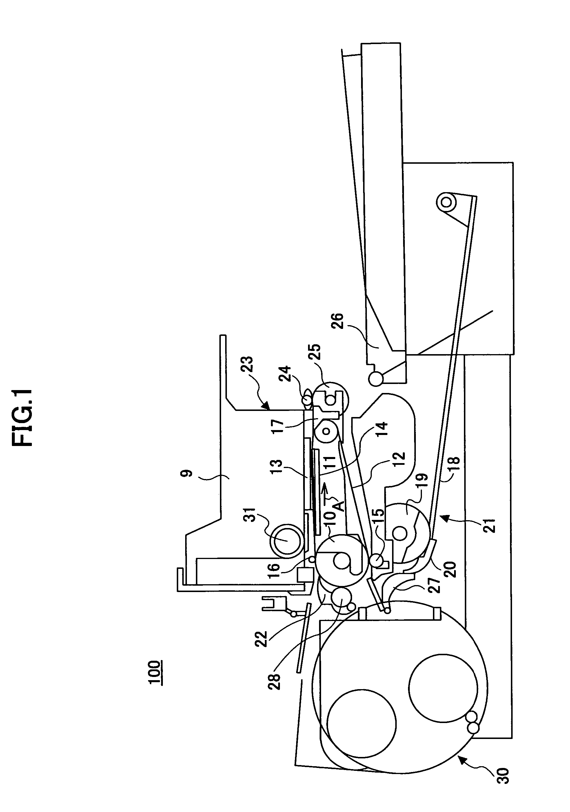
[0039]First, a basic structure of the printer is discussed. FIG. 1 is a front view showing an example of a structure of the inkjet printer.

[0040]A printer 100 includes a printing mechanism 23 having a carriage 9 movably held in a main scanning direction crossing a conveying direction of a paper by a driving part. The printer 100 includes a conveying part 21 conveying a paper situated in a paper feeding tray 18 to the paper discharge tray 26 via a position facing the printing mechanism 23.

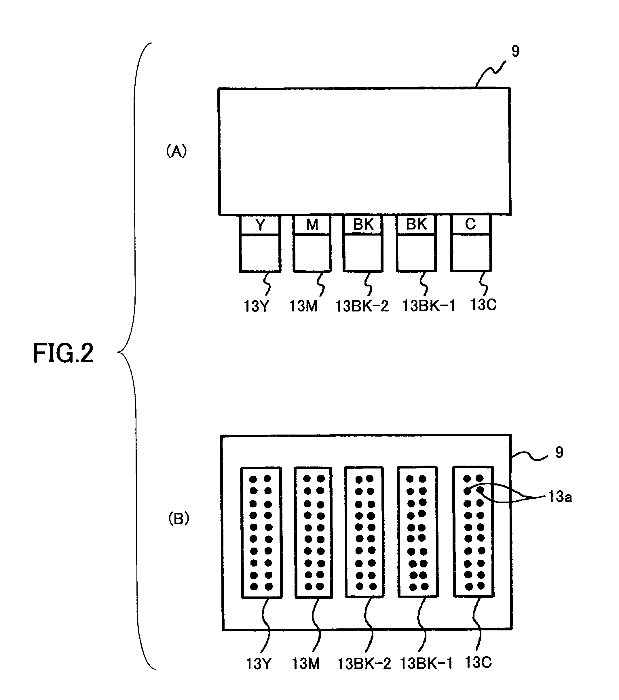
[0041]Head 13 having plural jet openings for jetting ink liquid having colors of C (cyan), B (black), M (magenta), and Y (yellow) to the paper are provided in the carriage 9 of the printing mechanism 23.

[0042]The conveying part 21 includes the paper feeding tray 18, a paper feeding ...


PUM


Abstract

An image forming apparatus includes a head part having a jet opening part configured to jet ink, a moisture retention cap configured to maintain moisture by covering the jet opening part, and a suction part configured to suction ink situated at the jet opening part. A suction cap having the suction part is provided separately from the moisture retention cap. The image forming apparatus includes a shutter member configured to open or close an opening part of the suction cap. The shutter member comes in contact with a perimeter of an edge part forming the opening part of the suction cap in a case where the shutter member is closed.

Description

BACKGROUND[0001]1. Technical Field[0002]The present disclosure generally relates to image forming apparatuses, and more specifically an image forming apparatus including a head part having a jet opening configured to jet ink, a moisture retention cap configured to maintain moisture by closing the jet opening part, and a suction part configured to suction ink situated at the jet opening part.[0003]2. Description of the Related Art[0004]An inkjet printer as an image forming apparatus which jets an ink drop from a jet opening part of a head part so as to form an image on a recording medium is well known. A water type ink composed of a pigment and a solvent wherein a wetting agent (humectant) and penetrating agent are included in water, is used as ink liquid for such an inkjet printer. In an inkjet printer using the ink liquid, ink viscosity is increased due to evaporation of the ink solvent at a head jet opening so that the jet opening is clogged up or closed due to the adhesion of dus...

Claims


Application Information

Patent Timeline
Patent Type & Authority Patents(United States)
IPC IPC(8): B41J2/165
CPCB41J2/16511
Inventor ISHIKAWA, KAZUMASA
Owner RICOH KK
Why Eureka
Try Eureka