Bearing arrangement for a vehicle differential

a technology for differential bearings and vehicles, applied in the direction of bearing unit rigid support, gearing details, gearing, etc., can solve the problems of causing wear in the housing and on the cup

Inactive Publication Date: 2008-07-01
THE TIMKEN CO
View PDF17 Cites 24 Cited by
  • Summary
  • Abstract
  • Description
  • Claims
  • Application Information

AI Technical Summary

Problems solved by technology

While the adjustors confine the cups of the bearings axially, they do not prevent the cups from rotating in the housing, and such rotation can produce wear in the housing and on the cups as well.

Method used


Image

  • Bearing arrangement for a vehicle differential
  • Bearing arrangement for a vehicle differential
  • Bearing arrangement for a vehicle differential

Examples


Embodiment Construction

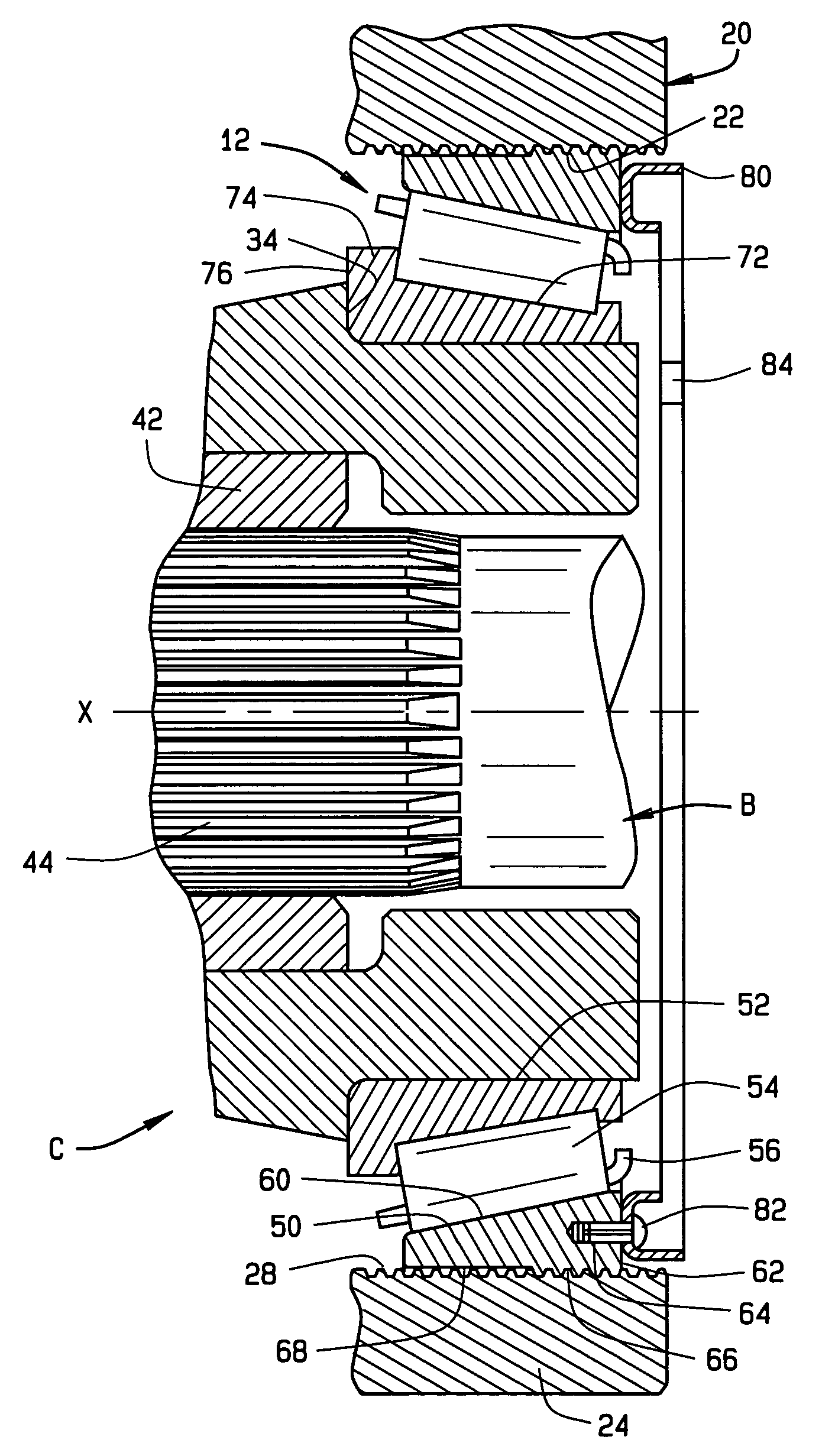
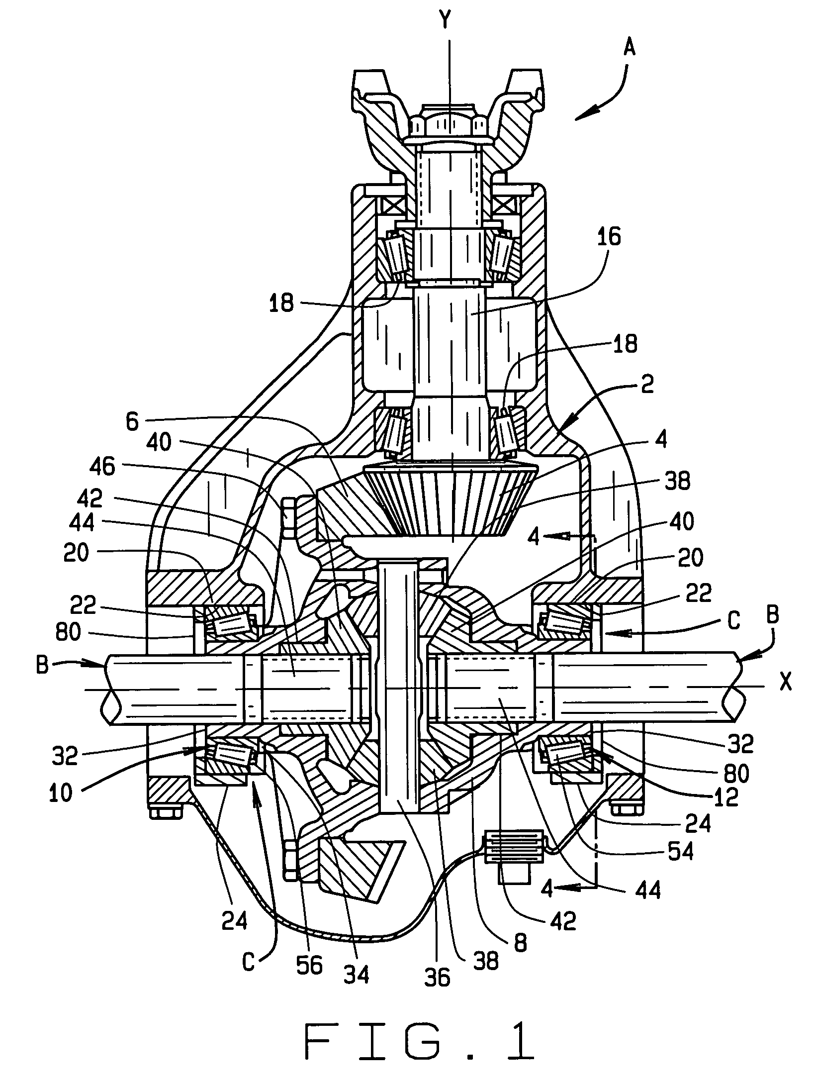
[0019]Referring now to the drawings, a vehicle differential A (FIG. 1) delivers torque to two axle shafts B which extend out to road wheels to which they are coupled. The differential A enables the axle shafts B to rotate at different angular velocities while delivering torque to both of them, a condition encountered when negotiating turns.

[0020]In very basic terms, the differential A includes (FIG. 1) a housing 2, a pinion 4, a ring gear 6 driven by the pinion 4, and a carrier 8 to which the ring gear 6 is attached, so that the pinion 4 likewise drives the carrier 8. The differential A also includes a bearing arrangement C that supports the carrier 8 in the housing 2. The pinion 4 rotates about a longitudinal axis Y, whereas the ring gear 6 and carrier 8 rotate about a transverse axis X, this rotation being accommodated by the bearing arrangement C which includes two single row tapered roller bearings 10 and 12 mounted in opposition—indeed, in the direct configuration. As such the ...


PUM


Abstract

A vehicle differential includes a housing having bearing seats and a carrier provided with stub shafts which project into the bearing seats. The carrier is supported in the housing on two single row tapered roller bearings which allow the carrier to rotate, but confine it radially and axially. The housing also contains a beveled pinion which meshes with a beveled ring gear that is attached to the carrier. The two bearings are mounted in opposition and each includes a cup that is located in the bearing seat for that bearing, a cone that fits around the stub axle that projects into that bearing seat, and tapered rollers located between the cup and cone. Each bearing seat contains an internal thread and the bearing cup which fits into the seat has an external thread that engages the internal thread. Each cup also carries a locking ring which is engaged by an adjustment tool to turn the cup, but is later deformed into the housing to secure the cup against rotation. By rotating the cups in their bearing seats, one can adjust the setting of the bearings and the mesh setting of the pinion and ring gear.

Description

STATEMENT REGARDING FEDERALLY SPONSORED RESEARCH OR DEVELOPMENT[0001]Not ApplicableBACKGROUND OF THE INVENTION[0002]This invention relates in general to antifriction bearings and more particularly antifriction bearings for vehicle differentials.[0003]The typical differential for an automotive vehicle has a housing in which meshed pinion and ring gears rotate, the former being connected to the transmission for the vehicle and the other being on a differential carrier having stub shafts which rotate in bearings set into the housing. The carrier has a cross shaft on which a pair of beveled gears rotate, and those bevel gears mesh with more bevel gears that are connected to the axle shafts which extend away from the carrier to driven road wheels. The bevel gears connected to the axle shafts have the capacity to rotate within the differential carrier at different angular velocities to compensate for the different angular velocities at which the two axle shafts will rotate when the vehicl...

Claims


Application Information

Patent Timeline
Patent Type & Authority Patents(United States)
IPC IPC(8): F16C23/00F16C25/00F16C43/00F16C19/36F16C19/54F16C25/06F16C33/58F16C33/60F16C35/067F16C35/077F16H48/08F16H57/02
CPCF16C19/364F16C19/548F16C25/06F16C33/60F16H48/08F16H57/021F16H57/037F16C35/067F16C2361/61F16H2048/405F16C19/547F16C2226/60
Inventor FAHRNI, JR., GLENN R.MILAM, DAVID L.MARCELLI, MICHAEL F.MARKS, CHRISTOPHER S.OBENG, KOFI P.RUSSELL, SCOTT D.ROUBANES, BYRONSTOFFER, GARY A.
Owner THE TIMKEN CO
Why Eureka
Try Eureka