Spiral wound fuel stabilization unit for fuel de-oxygenation

a fuel stabilization unit and wound technology, applied in the direction of liquid degasification, separation process, filtration separation, etc., can solve the problems of increasing the temperature of fuel, increasing the rate at which oxidative reactions occur, and limited usable cooling capacity of a particular fuel, so as to reduce weight, facilitate filtration, and efficient utilization of space

Active Publication Date: 2008-07-01
MEMBRANE TECH & RES +1
View PDF108 Cites 25 Cited by
  • Summary
  • Abstract
  • Description
  • Claims
  • Application Information

AI Technical Summary

Benefits of technology

[0011]Accordingly, the deoxygenator of this invention provides a permeable membrane system that can remove dissolved oxygen from fuel down to the level required to suppress coke formation, and that is configurable to efficiently utilize space, reduce weight, is easily scalable, performs predictably, and that can be manufactured economically.

Problems solved by technology

However, increasing the temperature of fuel also increases the rate at which oxidative reactions occur.
The usable cooling capacity of a particular fuel is limited by coke formation and deposition, which is dependent on the amount of dissolved oxygen present within the fuel due to prior exposure to air.
In other words, the less dissolved oxygen within the fuel, the higher the temperature before coke buildup becomes a problem.
Fuels that currently have improved coking performance are generally more expensive or require additives, and therefore are not always available.
As is appreciated permeable membranes are difficult to manufacture and are limited in size and construction by sizing and economic factors.
Membrane bundles are difficult to scale because performance is highly dependent on spacing and geometry and thus hard to predict.

Method used


Image

  • Spiral wound fuel stabilization unit for fuel de-oxygenation
  • Spiral wound fuel stabilization unit for fuel de-oxygenation
  • Spiral wound fuel stabilization unit for fuel de-oxygenation

Examples


Embodiment Construction

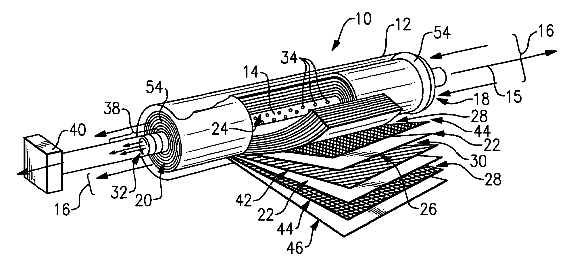
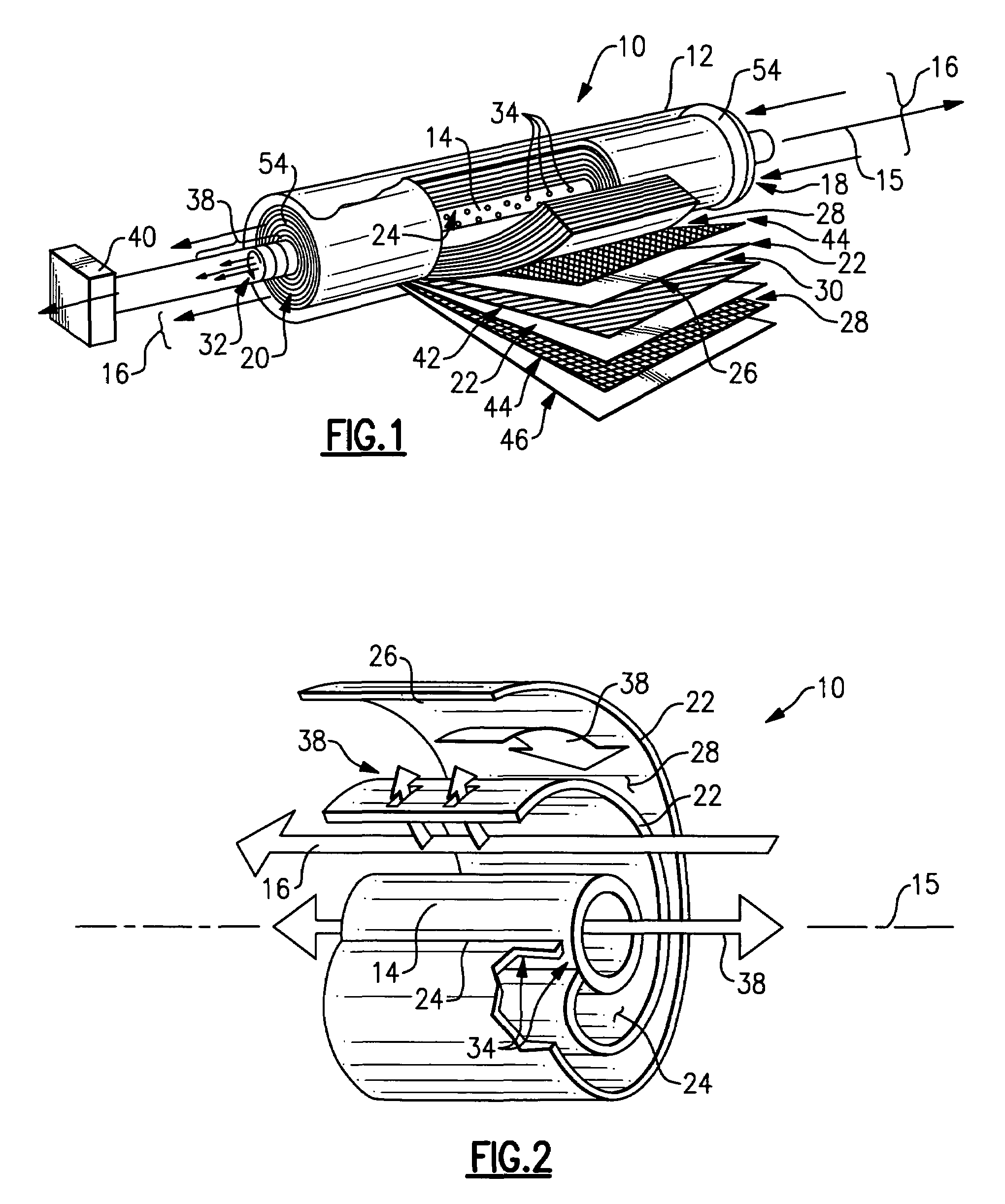
[0017]Referring to FIG. 1 a spiral wound fuel deoxygenator 10 includes an exhaust tube 14 disposed along axis 15 within a housing 12. The housing 12 defines an inlet 18 and outlet 20 for fuel flow 16. Fuel flow 16 entering the inlet 18 including some portion of dissolved oxygen 38. A permeable membrane 22 is spirally wrapped about the exhaust tube 14. The example permeable membrane 22 is a sheet having a first end 24 attached to the exhaust tube 14 and a second end 26 spirally wrapped about the exhaust tube 14. The example deoxygenator 10 includes a plurality of permeable membranes 22 that correspond with each other to form fuel passages 28 and exhaust passages 30.

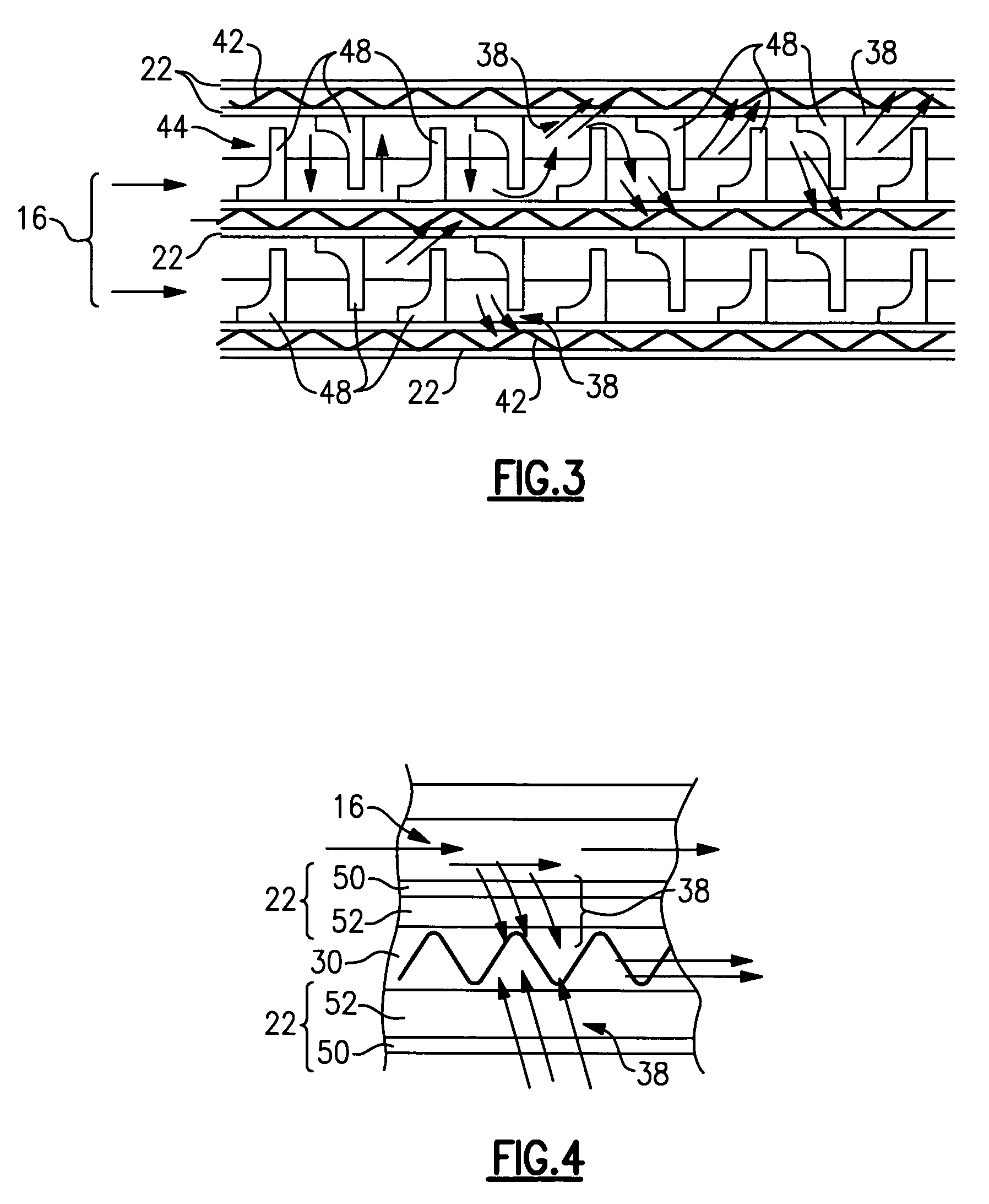
[0018]The fuel passages 28 and exhaust passages 30 alternate such that each fuel passage 28 is bounded on each adjacent side by an exhaust passage 30. An oxygen partial pressure differential is generated across the permeable membrane 22 to draw dissolved oxygen 38 from fuel in the fuel passage 28. In the example embodiment...


PUM

PropertyMeasurementUnit
thicknessaaaaaaaaaa
thicknessaaaaaaaaaa
thicknessaaaaaaaaaa

Abstract

A deoxygenator includes a plurality of permeable membranes spirally wound about an exhaust tube for removing dissolved oxygen from a hydrocarbon fuel. The permeable membrane is spirally wrapped about the exhaust tube and defines fuel passages and exhaust passages. The fuel passages and exhaust passages alternate such that each fuel passage is bounded on each adjacent side by an exhaust passage. An oxygen partial pressure differential is generated across the permeable membrane to draw dissolved oxygen from fuel in the fuel passage. The dissolved oxygen is then communicated through openings about the circumference of the exhaust tube and out the deoxygenator.

Description

BACKGROUND OF THE INVENTION[0001]This invention relates generally to a method and device for removing dissolved oxygen from fuels and more particularly to a spirally wound membrane for removing dissolved oxygen from liquid hydrocarbon fuels.[0002]Fuel can be utilized as a cooling medium for various systems of an energy conversion device. However, increasing the temperature of fuel also increases the rate at which oxidative reactions occur. The usable cooling capacity of a particular fuel is limited by coke formation and deposition, which is dependent on the amount of dissolved oxygen present within the fuel due to prior exposure to air. Reduction of the amount of dissolved oxygen within the fuel can result in the reduction of coke formed within a fuel delivery system of the energy conversion device.[0003]Decreasing the amount of dissolved oxygen present within fuel reduces the formation of insoluble products referred to as “coke” or “coking”. Reducing the amount of oxygen dissolved ...

Claims


Application Information

Patent Timeline
Patent Type & Authority Patents(United States)
IPC IPC(8): B01D53/22B01D63/10
CPCB01D19/0031B01D19/0036B01D63/10B64D37/32B01D61/00Y02T50/44Y02T50/40B01D19/00B01D69/00
Inventor SPADACCINI, LOUIS J.CORDATOS, HARRYTILLMAN, THOMAS GREGORYCHEN, ALEXANDER G.CHIAPPETTA, LOUISIRISH, JAMES R.LAMM, FOSTER PHILLIPJONES, STEPHEN R.
Owner MEMBRANE TECH & RES
Why Eureka
Try Eureka