Rotary electrical switching device

Inactive Publication Date: 2008-07-01
IN2TEC
View PDF6 Cites 2 Cited by
  • Summary
  • Abstract
  • Description
  • Claims
  • Application Information

AI Technical Summary

Benefits of technology

[0012]In an additional alternative embodiment, the first surface of one of said substrate layers is provided with a plurality of separate contacts that are arranged in a circle, said circle being centred on the axis of rotation of the actuator member such that, as the rotary actuator rotates, the engagement of its projection against the second surface of the deformable substrate layer causes said plurality of contacts to come into contact sequentially with the conducting contact on the first surface of the other substrate layer. In this way, the device can advantageously be set up to give positional output as the actuator is rotated.
[0013]In a useful development, th

Problems solved by technology

Electrical switches are well known, but typically suffer from the disadvantage that they are not adequately sealed from the outside environment and, in particular, do not provide satisfactory protection against the ingress of water.
For example, known rotary switches generally comprise an ac

Method used


Image

  • Rotary electrical switching device
  • Rotary electrical switching device
  • Rotary electrical switching device

Examples


Embodiment Construction

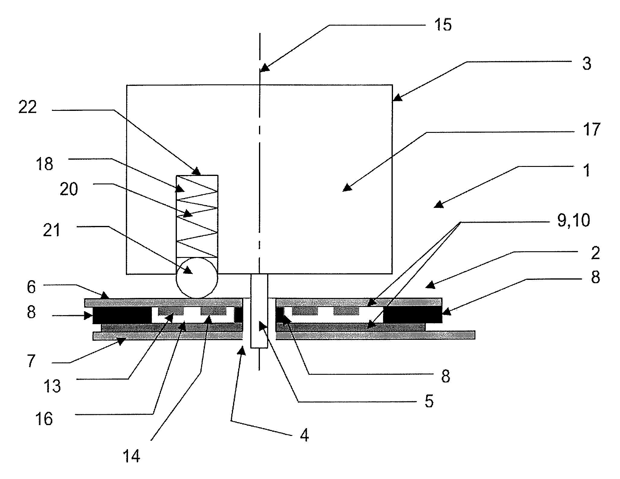
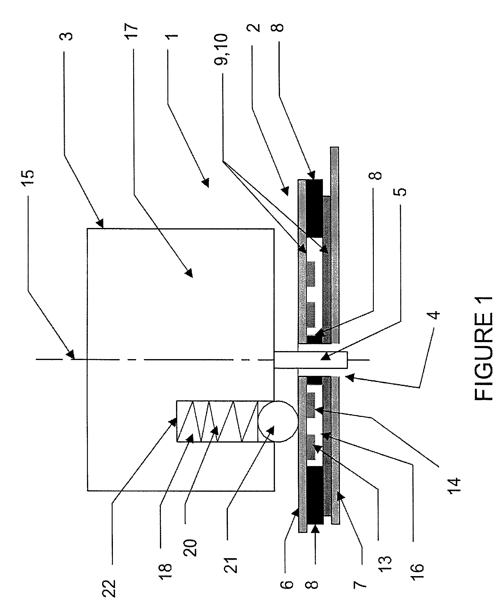
[0022]Referring to FIG. 1, there is shown a rotary electric switch 1 comprising a base 2 and a rotary actuator 3, the base 2 having a through-hole 4 at its centre, in which an axle 5 of the rotary actuator 3 is mounted, a first substrate layer 6, and a second substrate layer 7 overlying the first substrate layer 6 so as to be parallel thereto. The two layers 6, 7 are furthermore separated apart by an adhesive 8, which joins the radially outer and inner edges of the substrate layers 6, 7 in a sealing fashion. Each of the substrate layers 6, 7 has a first surface 9, 10 which faces the other substrate layer 6, 7 and a second surface 11, 12 opposite said first surface 9, 10. The first surface 9 of the first substrate layer 6 has a pair of concentric, radially spaced, generally arcuate conducting tracks 13, 14 mounted thereon, which are centred on the axis of rotation 15 of the rotary actuator 3, and the first surface 10 of the second substrate layer 7 has a conducting plate 16 mounted t...


PUM


Abstract

A rotary electric switch 1 comprises a base 2 having a rotary actuator 3 mounted thereon, the base 2 including a pair of substantially parallel, spaced apart substrate layers 6, 7. Each layer 6, 7 has a first surface 9, 10 which faces the other substrate layer 7, 6 and a second surface 11, 12 which faces away from the other substrate layer 7, 6, the first surface 9, 10 of each layer having an electrically conducting contact 13, 14, 16 provided thereon. At least one of the substrate layers 6, 7 is deformable towards the other so as to effect an electrical connection between the contacts 13, 14, 16 on the two layers 6, 7, and the rotary actuator 3 includes a projection 21 which engages against the second surface 11 of said deformable substrate layer 6 so as to press it towards the other layer 7 in the immediate vicinity of the projection 21. In this way, rotation of the rotary actuator 3 moves the projection 21 relative to the substrates 6, 7 and hence varies the point of electrical connection between the contacts 13, 14, 16.

Description

BACKGROUND OF THE INVENTION[0001]The present invention relates to a rotary electrical switch, preferably for use in a rotary encoder.[0002]Electrical switches are well known, but typically suffer from the disadvantage that they are not adequately sealed from the outside environment and, in particular, do not provide satisfactory protection against the ingress of water. For example, known rotary switches generally comprise an actuator that is required to come into direct contact with electrical contacts in order affect switching states, but said requirement for direct contact makes it difficult to satisfactorily seal the circuitry of the switch from the environment. Furthermore, known electrical switches comprise a domed-shaped conductive contact mounted onto a circuit layer, which, when depressed, makes contact with a further conductive contact mounted within it, on the same circuit layer. Such switches are typically overlaid by a sheet or membrane of some kind such that the actuato...

Claims


Application Information

Patent Timeline
IPC IPC(8): H01H3/08H01H1/40H01H19/63
CPCH01H19/63H01H1/403H01H1/16H01H1/50H01H19/10H01H19/635
Inventor LEWISON, JOHN
Owner IN2TEC
Why Eureka
Try Eureka