Sound attenuating structures

a technology of attenuating structures and sound, applied in fireproofing, instruments, walls, etc., can solve the problems of breaking the mass density law, lrsm can still be fairly thick and heavy, current designs still suffer, etc., and achieve the effect of significantly reducing effects

a technology of attenuating structures and sound, applied in fireproofing, instruments, walls, etc., can solve the problems of breaking the mass density law, lrsm can still be fairly thick and heavy, current designs still suffer, etc., and achieve the effect of significantly reducing effects

US7395898B2Active Publication Date: 2008-07-08THE HONG KONG UNIV OF SCI & TECH

Image

  • Sound attenuating structures
  • Sound attenuating structures
  • Sound attenuating structures

Examples


Embodiment Construction

[0025]The current invention relates to a new type of LRSM design. Basically, the local oscillators can be regarded as composed of two components: the mass m of the oscillator, and the spring K of the oscillator. It is usually counter productive to increase m since that will increase the overall weight of the panels. Hence one should choose to lower K. However, a lower K is usually associated with soft materials, which would be difficult to sustain structurally. In preferred embodiments of the present invention, however, a lower K is achieved through geometric means as will be seen from the following.

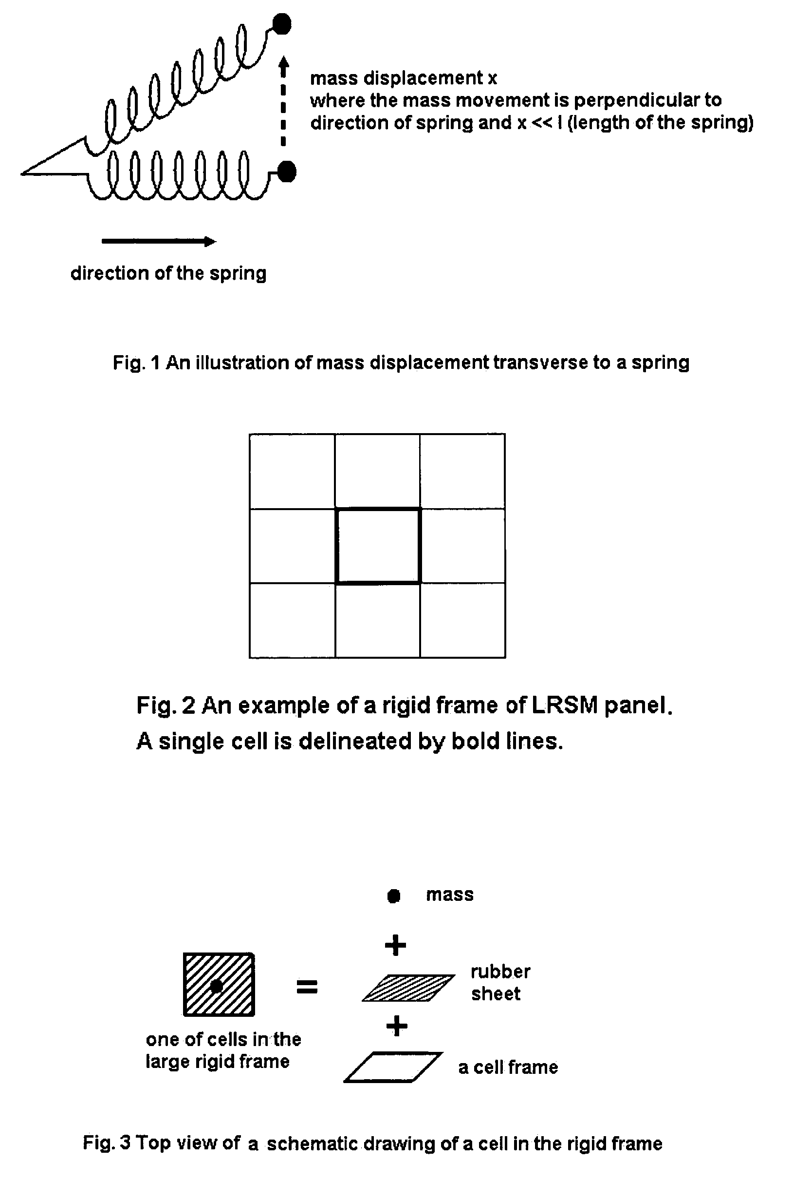
[0026]Consider the usual mass-spring geometry whereby the mass displacement x is equal to the spring displacement, so that the restoring force is given by Kx. Consider the case in which the mass displacement is transverse to the spring as shown in FIG. 1. In that case the mass displacement x will cause a spring elongation in the amount of (1 / 2)*l*(x / l)2=x2 / 2l, where l is the length of th...


PUM

PropertyMeasurementUnit
massaaaaaaaaaa
thicknessaaaaaaaaaa
massaaaaaaaaaa

Abstract

There is disclosed a sound attenuation panel comprising, a rigid frame divided into a plurality of individual cells, a sheet of a flexible material, and a plurality of weights. Each weight is fixed to the sheet of flexible material such that each cell is provided with a respective weight and the frequency of the sound attenuated can be controlled by suitable selecting the mass of the weight.

Description

FIELD OF THE INVENTION[0001]This invention relates to novel sound attenuating structures, and in particular to locally resonant sonic materials (LRSM) that are able to provide a shield or sound barrier against a particular frequency range and which can be stacked together to act as a broad-frequency sound attenuation shield.BACKGROUND OF THE INVENTION AND PRIOR ART[0002]In recent years, a new class of sonic materials has been discovered, based on the principle of structured local oscillators. Such materials can break the mass density law of sound attenuation, which states that in order to attenuate sound transmission to the same degree, the thickness, or mass per unit area, of the solid panel has to vary inversely with the sound frequency. Thus with the conventional sound attenuation materials low frequency sound attenuation can require very thick solid panels, or panels made with very high density material, such as lead.[0003]The basic principles underlying this new class of materi...

Claims


Application Information

Patent Timeline
08 Jul 2008
Publication
US7395898B2
IPC
E04B1/82; B32B; G10K11/16; E04B; E04B1/86; E04B1/94; E04B2/02; G10K11/162; G10K11/168; G10K11/172; G10K11/36
CPC
G10K11/172; G10K11/00; G10K11/16
Inventors
YANG, ZHI YU; WEN, WEIJIA