Amplitude and phase controlled adaptive optics system

a phase control and adaptive optics technology, applied in the field of adaptive optics methods and systems, to achieve the effect of optimal compensation

Active Publication Date: 2008-07-08
LOCKHEED MARTIN CORP
View PDF11 Cites 27 Cited by
  • Summary
  • Abstract
  • Description
  • Claims
  • Application Information

AI Technical Summary

Benefits of technology

[0011]The present invention may offer a number of benefits and/or advantages. For example, the system produces optimal compensation by measur

Problems solved by technology

The system uses intensity error to control the first deformable

Method used


Image

  • Amplitude and phase controlled adaptive optics system
  • Amplitude and phase controlled adaptive optics system
  • Amplitude and phase controlled adaptive optics system

Examples


Embodiment Construction

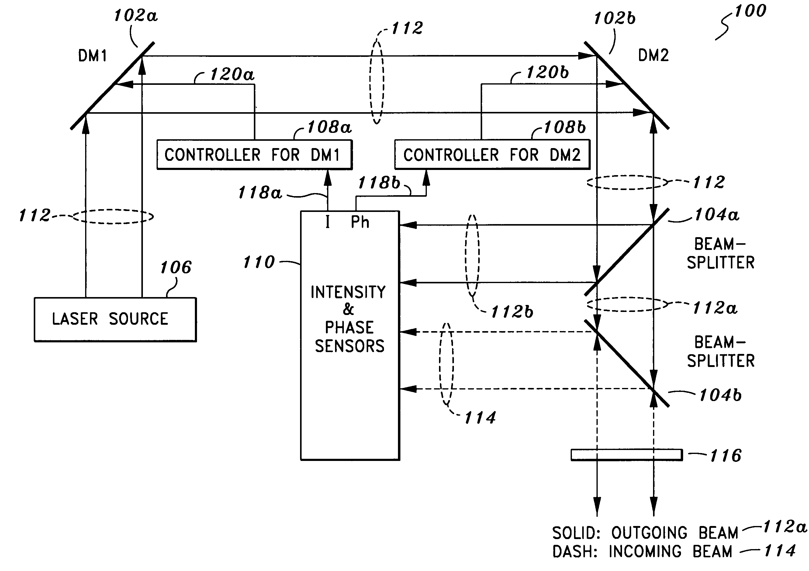
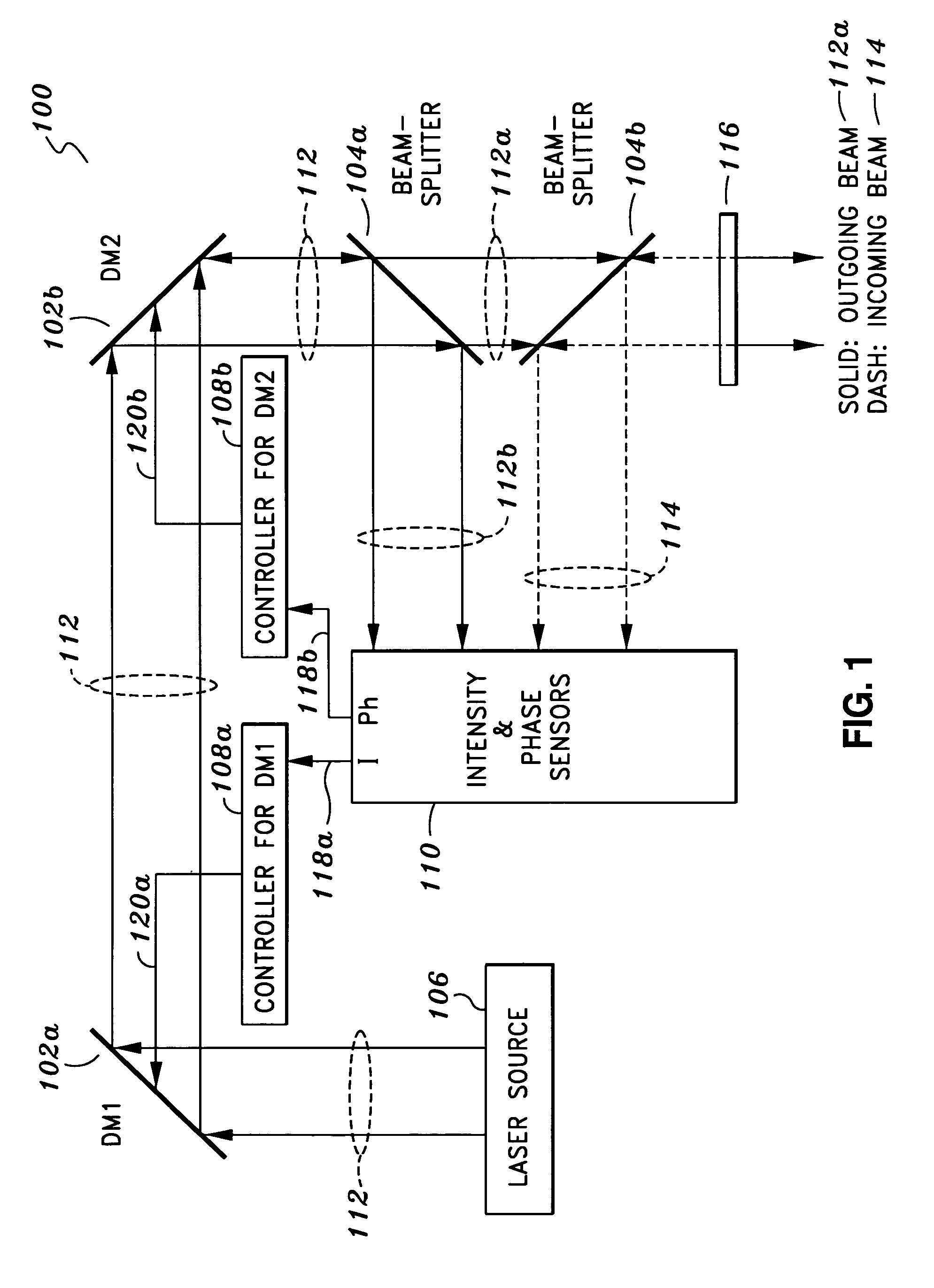
[0019]One or more embodiments of the present invention will now be described. FIG. 1 illustrates a dual-DM (deformable mirror) system according to one embodiment of the present invention. The system 100 includes a first deformable mirror “DM1”102a and a second deformable mirror “DM2”102b, corresponding controllers 108a-b for DM1102a and DM2102b, two beam splitters 104a-b, a laser source 106, and a detection module 110 having a number of intensity and phase sensors. It should be understood that actuators (not shown) are used to control the physical movements of DM1 and DM2102a-b based on the control signals 120a-b provided by the corresponding controllers 108a-b.

[0020]As shown in FIG. 1, the system 100 generates an outgoing beam 112a and receives an incoming beam 114. It should be understood that in this particular illustration the outgoing beam 112a and the incoming beam 114 are shown as overlapping each other at the beam exit / entry point 116. With respect to the outgoing beam 112a...


PUM


Abstract

An adaptive optics system is provided. The system includes a light source, a pair of deformable mirrors and a detection module. The light source is configured to provide an outgoing beam. The outgoing beam has an amplitude and a phase. The first deformable mirror is configured to reflect the outgoing beam and adjust its associated amplitude. The second deformable mirror is configured to reflect the outgoing beam reflected from the first deformable mirror and adjust its associated phase. The detection module is configured to detect an incoming beam and the reflected outgoing beam from the second deformable mirror and generate certain signals. The signals are used to control the first and second deformable mirrors such that the amplitude of the outgoing beam is the same as that of the incoming beam and the phase of the outgoing beam is opposite that of the incoming beam.

Description

CROSS-REFERENCE(S) TO RELATED APPLICATION(S)[0001]Not Applicable.STATEMENT AS TO RIGHTS TO INVENTIONS MADE UNDER FEDERALLY SPONSORED RESEARCH OR DEVELOPMENT[0002]Not Applicable.BACKGROUND OF THE INVENTION[0003]The present invention generally relates to methods and systems for providing adaptive optics, and in particular to methods and systems for providing adaptive optics using amplitude and phase.[0004]Typical adaptive optics systems utilize deformable mirror (DM) actuators to compensate for the optical effects introduced by the turbulence in the Earth's atmosphere and distortions produced by the optical elements between the distant object and its local sensors. Such adaptive optics systems command the DM actuators while minimizing the measured wavefront phase error and set the DM actuators so that the outgoing laser's phase is opposite that of an incoming beacon. The disadvantage of the foregoing technique is that it does not work well in a strong turbulent or scintillation condit...

Claims


Application Information

Patent Timeline
IPC IPC(8): G01J1/20
CPCG02B26/06
Inventor PHAM, ICH V.VASUDEVAN, GOPAL
Owner LOCKHEED MARTIN CORP
Why Eureka
Try Eureka