
Power supply detection circuit biased by multiple power supply voltages for controlling a signal driver circuit

Active Publication Date: 2008-07-08
NAT SEMICON CORP
View PDF2 Cites 42 Cited by
  • Summary
  • Abstract
  • Description
  • Claims
  • Application Information

AI Technical Summary

Benefits of technology

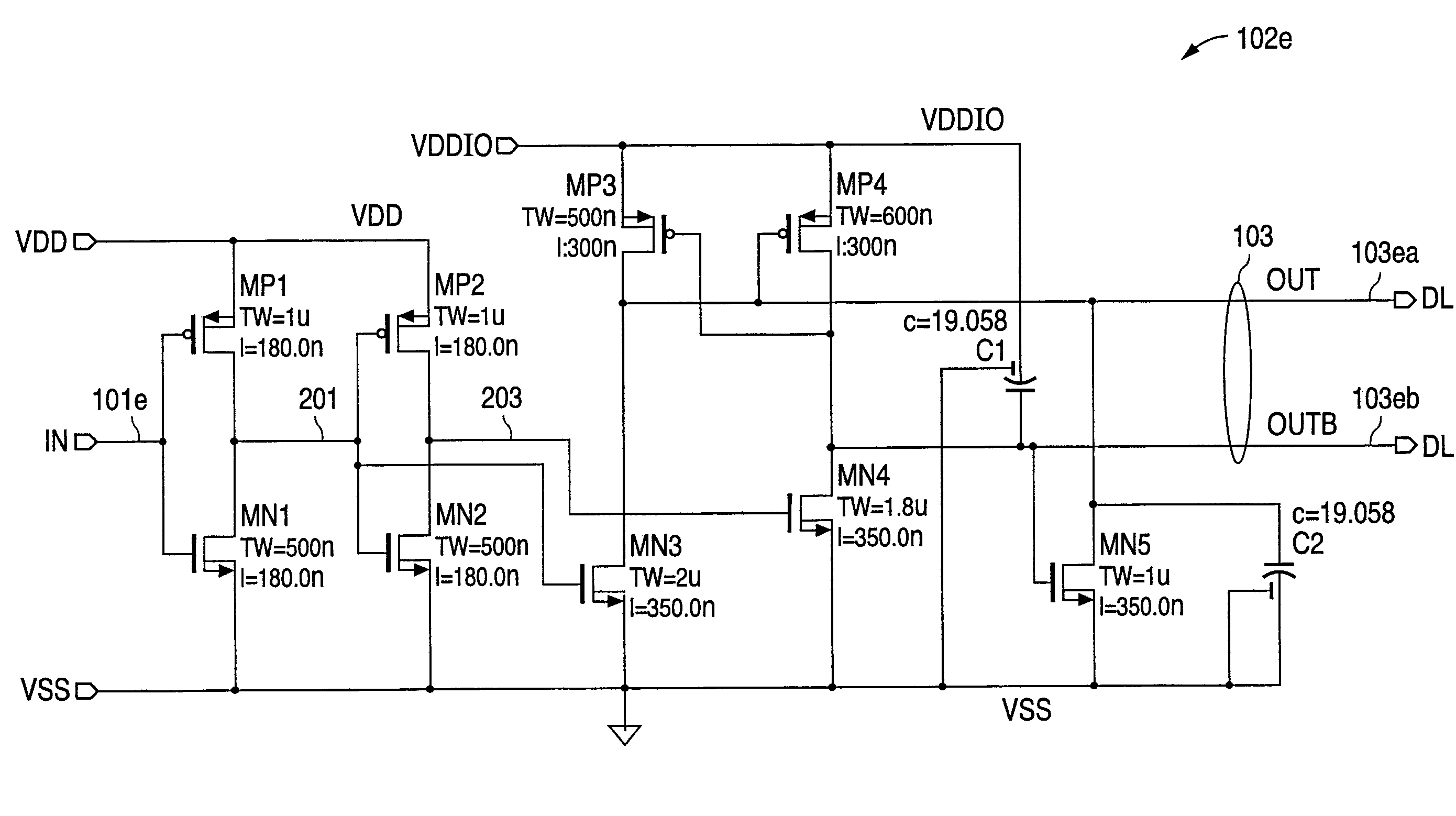
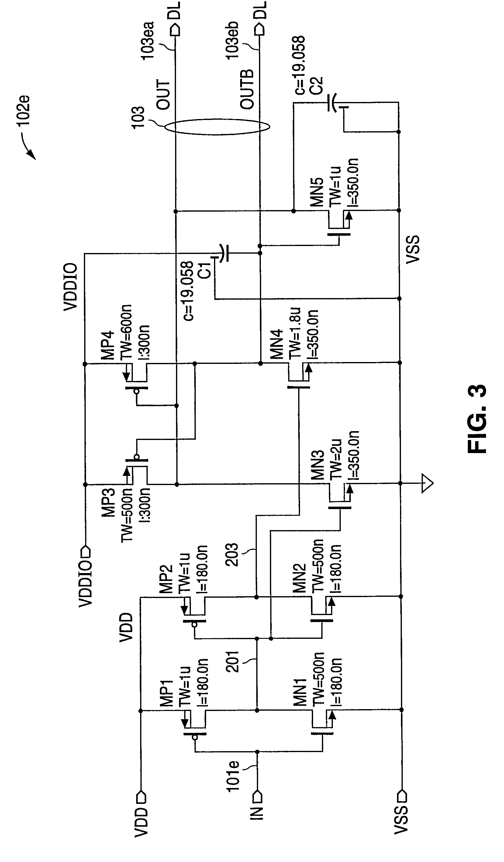
[0008]In accordance with the presently claimed invention, a power supply detection circuit biased by at least two power supply voltages for controlling a signal driver circuit is provided. Upstream and downstream amplifiers, powered by upstream and downstream power supply voltages, respectively, process an original control signal to produce a differential signal via output signal electrodes. Capacitances coupling respective ones of the ou

Problems solved by technology

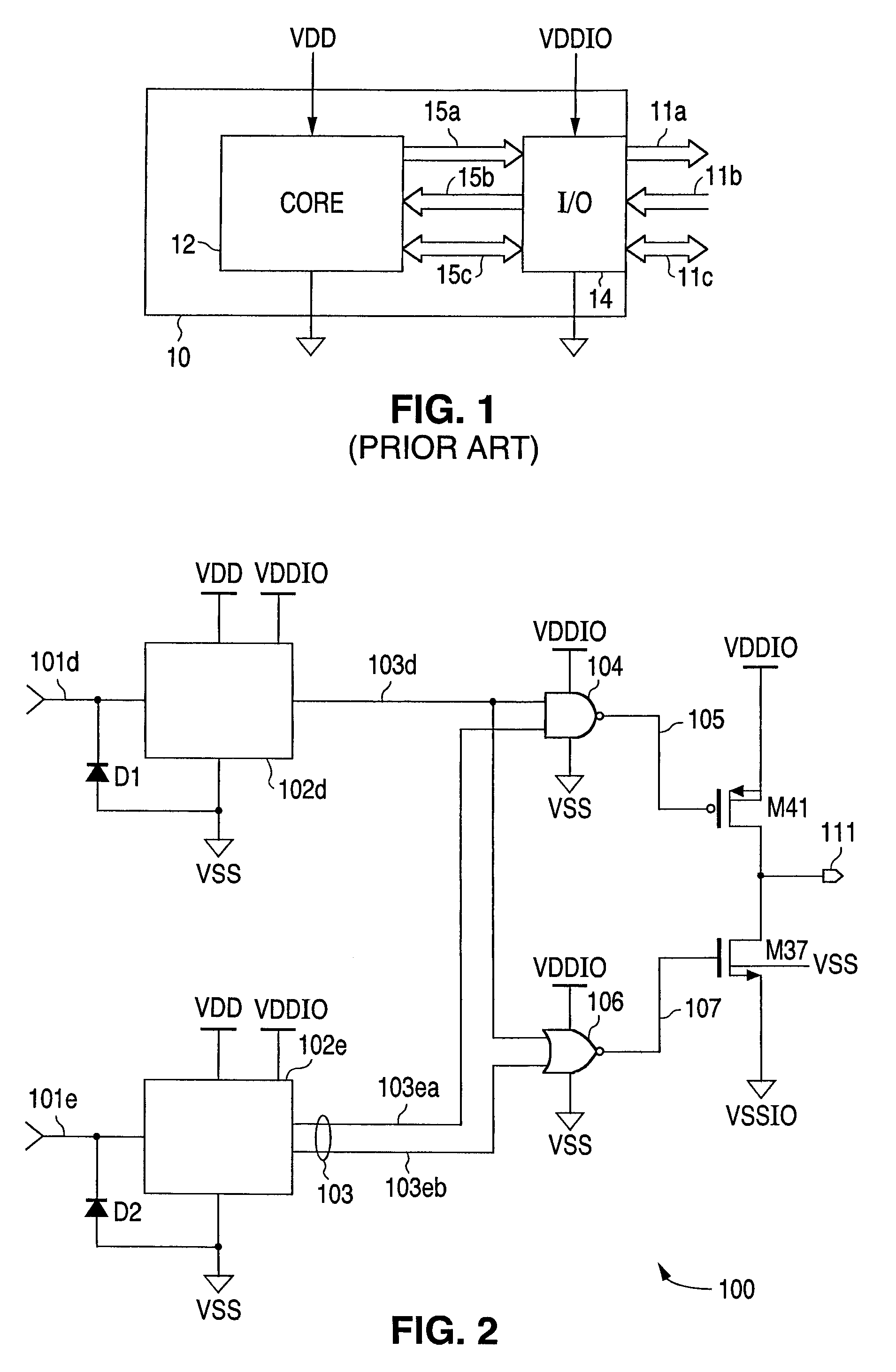
This is often problematic since the output enable signal is typically generated by the core circuit 12 which is powered by the core power supply voltage VDD, which has not yet been applied.

Method used


Image

  • Power supply detection circuit biased by multiple power supply voltages for controlling a signal driver circuit
  • Power supply detection circuit biased by multiple power supply voltages for controlling a signal driver circuit
  • Power supply detection circuit biased by multiple power supply voltages for controlling a signal driver circuit

Examples


Embodiment Construction

[0014]The following detailed description is of example embodiments of the presently claimed invention with references to the accompanying drawings. Such description is intended to be illustrative and not limiting with respect to the scope of the present invention. Such embodiments are described in sufficient detail to enable one of ordinary skill in the art to practice the subject invention, and it will be understood that other embodiments may be practiced with some variations without departing from the spirit or scope of the subject invention.

[0015]Throughout the present disclosure, absent a clear indication to the contrary from the context, it will be understood that individual circuit elements as described may be singular or plural in number. For example, the terms “circuit” and “circuitry” may include either a single component or a plurality of components, which are either active and / or passive and are connected or otherwise coupled together (e.g., as one or more integrated circ...


PUM


Abstract

A power supply detection circuit biased by at least two power supply voltages for controlling a signal driver circuit. Upstream and downstream amplifiers, powered by upstream and downstream power supply voltages, respectively, process an original control signal to produce a differential signal via output signal electrodes. Capacitances coupling respective ones of the output signal electrodes to the downstream power supply voltage and the circuit reference potential discharge and charge respective ones of the output signal electrodes in relation to initial receptions of the upstream and downstream power supply voltages and original control signal, following which voltage clamp circuitry maintains such discharged and charged states pending reception of the original control signal in a predetermined state.

Description

BACKGROUND OF THE INVENTION[0001]1. Field of the Invention[0002]The present invention relates to interface circuits for translating voltage levels of signals between circuits biased by unequal power supply voltages, and in particular, to such interface circuits with minimum power consumption during initial application of the power supply voltages.[0003]2. Related Art[0004]Referring to FIG. 1, a power supply detection circuit has become an essential part of the input / output (I / O) interface in digital and mixed signal integrated circuits, or “chips”, having multiple, e.g., two, power supplies. For example, a typical example of such a chip 10 includes, at a minimum, core circuitry 12 biased by a core power supply voltage VDD, and I / O interface circuitry 14 powered by another power supply voltage VDDIO. Typically, the core circuit 12 operates at a lower power supply voltage to minimize power consumption, while the I / O circuit 14 operates, at least in part, at a higher power supply volta...

Claims


Application Information

Patent Timeline
IPC IPC(8): H03L5/00
CPCH03K19/0016
Inventor KIANI, KHUSROW
Owner NAT SEMICON CORP
Learn More