Image forming apparatus

a technology of image forming and forming medium, which is applied in the direction of recording apparatus, instruments, electrographic processes, etc., can solve the problems of a lot of waiting outside time, and achieve the effects of improving the stability of image forming, reducing waiting time, and increasing the flatness of flexible recording medium

Inactive Publication Date: 2008-07-08
ADTEC ENG +1
View PDF6 Cites 10 Cited by
  • Summary
  • Abstract
  • Description
  • Claims
  • Application Information

AI Technical Summary

Benefits of technology

[0014]According to this configuration, the long flexible recording medium is conveyed in a state where it is flatly disposed on the endless belt of the belt conveyance mechanism. Image forming can be continuously conducted by the image forming unit on the portion of the long flexible recording medium that is flatly retained and conveyed on the endless belt. Thus, exposure processing can always be continued, whereby the waiting time can be reduced, many exposure process can be conducted in a short time, and productivity can be improved.
[0017]By configuring the image forming apparatus in this manner, the long flexible recording medium is sucked against the surface of the endless belt that is wound and flatly stretched between the at least two rollers, whereby image forming can be conducted while the flatness of the flexible recording medium is maintained as the flexible recording medium is conveyed. Therefore, the stability of image forming can be improved.
[0021]By configuring the image forming apparatus in this manner, the contact roller or the suction stage supports the undersurface of the endless belt that is wound and flatly stretched between the at least two rollers, and the flatness of the flexible recording medium is maintained via the endless belt. For this reason, image forming can be conducted in a state where even greater flatness is retained. Therefore, the stability of image forming can be further improved.

Problems solved by technology

For this reason, there may be a lot of waiting time outside the time in which exposure processing is being conducted.

Method used


Image

  • Image forming apparatus
  • Image forming apparatus
  • Image forming apparatus

Examples


Embodiment Construction

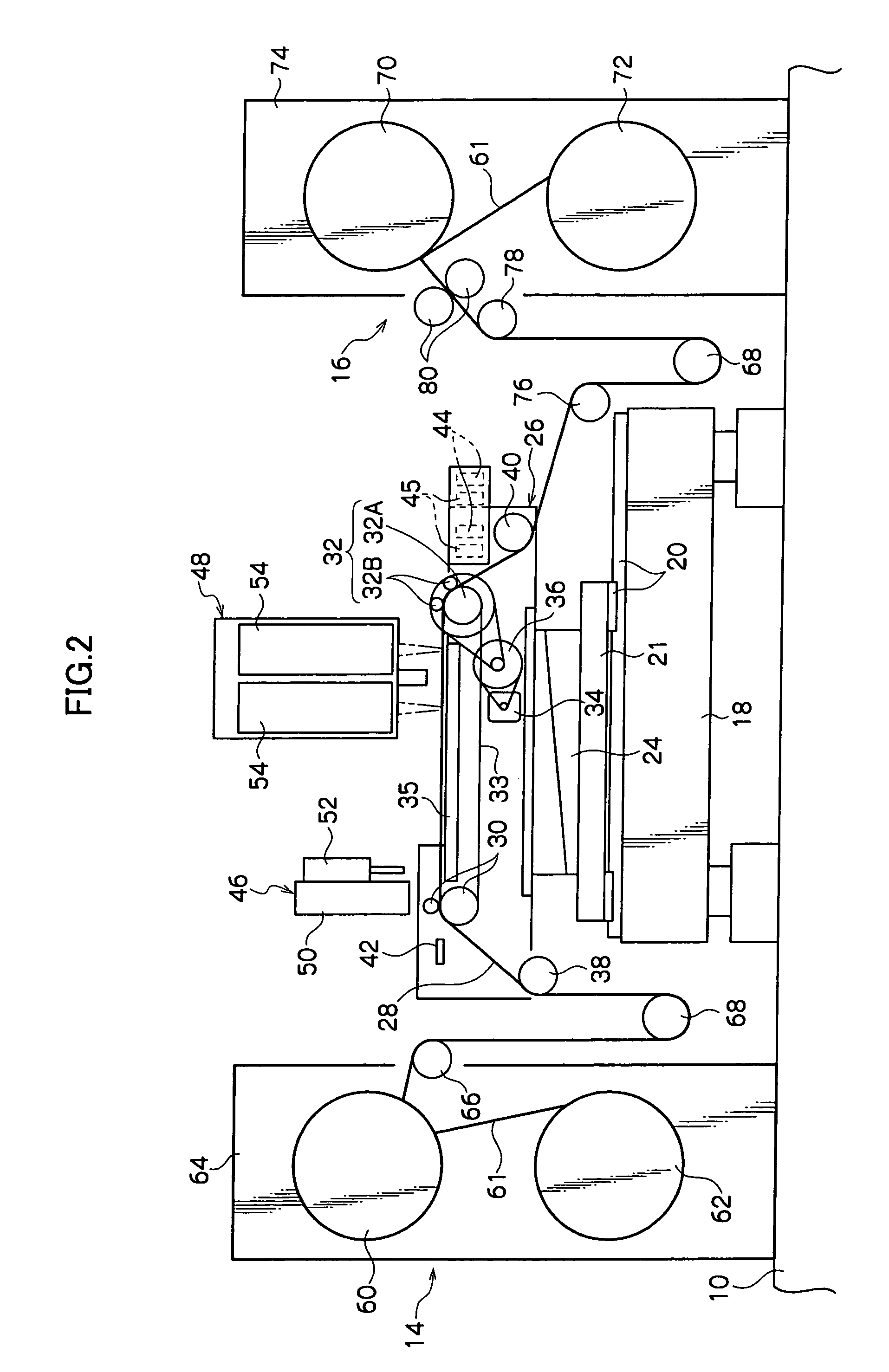
[0034]An embodiment of the image forming apparatus pertaining to the invention will now be described with reference to FIGS. 1 to 8.

[0035]The image forming apparatus pertaining to the embodiment of the invention is configured as an exposure apparatus that is automatically controlled by a control unit and conducts exposure processing with an exposure head by moving, in a main scanning direction, a flexible printed wiring board material that is a flexible recording medium formed in a long, band-like sheet, spatially modulating multi-beams emitted from light sources on the basis of modulation signals generated from image data by the control unit, and irradiating the flexible printed wiring board material with the spatially modulated multi-beams.

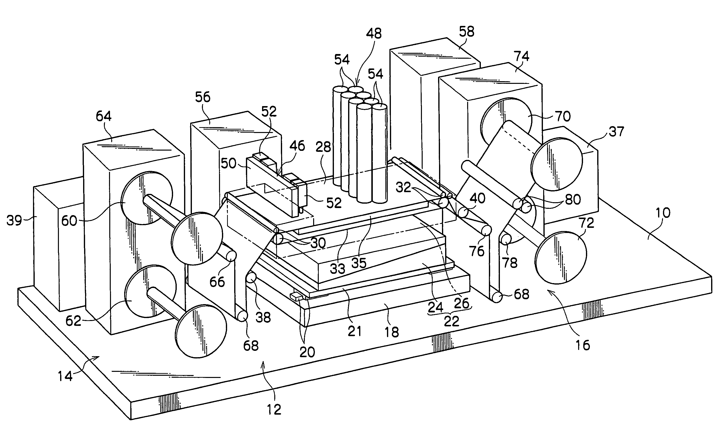
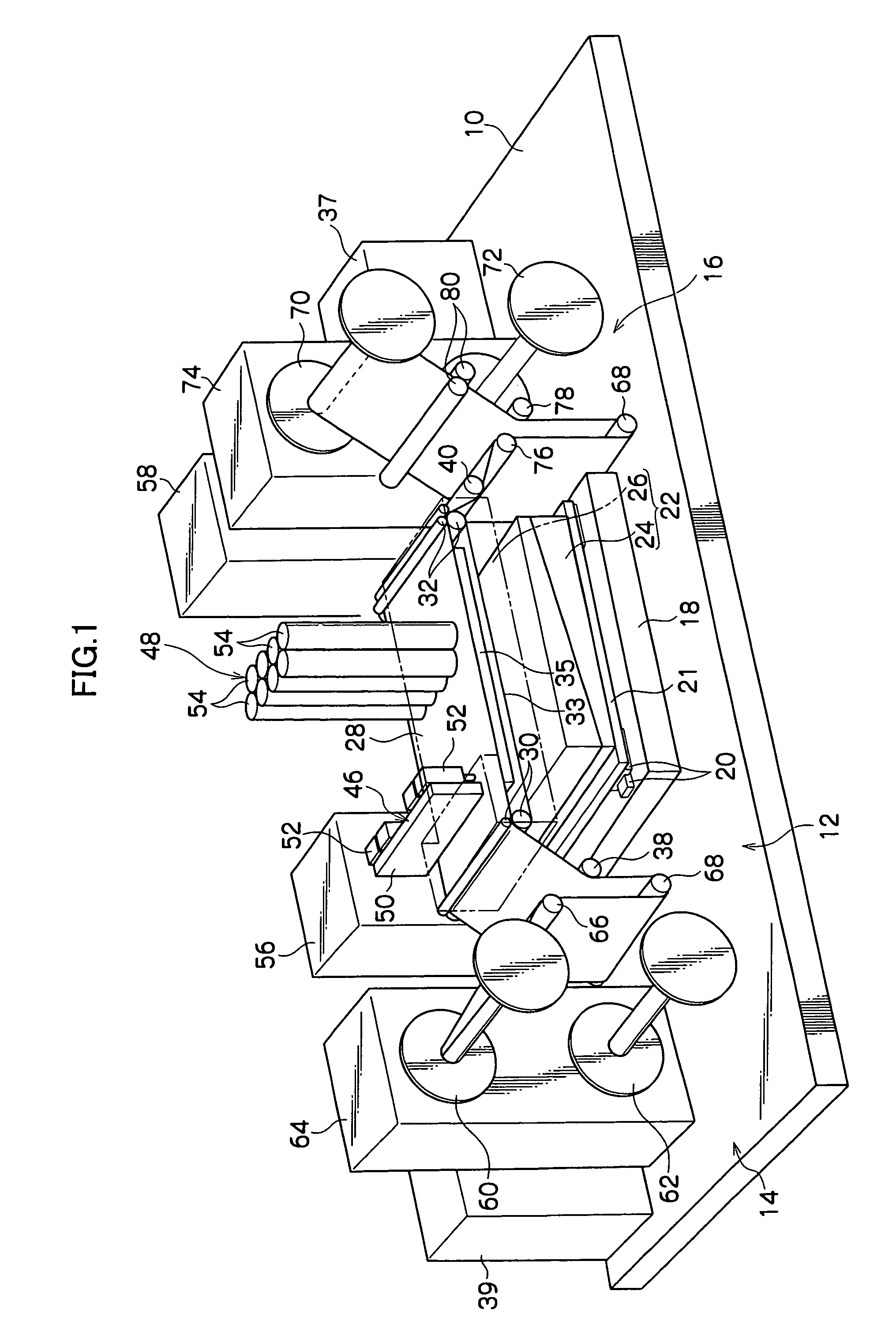
[0036]As shown in FIG. 1, the image forming apparatus includes a floor base 10, an exposure processing section 12, an unexposed recording medium supply section 14, and an exposed recording medium collection section 16. The exposure processing se...


PUM


Abstract

An image forming apparatus that forms images, while continuously conveying, a long flexible recording medium in a constant conveyance direction on a conveyance path, the image forming apparatus comprising: a belt conveyance mechanism that is disposed on the conveyance path and is configured by an endless belt wound between at least two rollers; and an image forming unit that conducts image forming on the long flexible recording medium being conveyed in a state where the long flexible recording medium is flatly disposed on the endless belt of the belt conveyance mechanism disposed on the conveyance path.

Description

CROSS-REFERENCE TO RELATED APPLICATION[0001]This application claims priority under 35 USC 119 from Japanese Patent Application No. 2004-284640, the disclosure of which is incorporated by reference herein.BACKGROUND OF THE INVENTION[0002]1. Field of the Invention[0003]The present invention relates to an image forming apparatus that forms an image on a long flexible recording medium.[0004]2. Description of the Related Art[0005]Among commonly used image forming apparatus, there are exposure apparatus, such as scanning type printed board exposure apparatus, laser photoplotters and laser printers, that form a desired image on a recording medium by scanning the recording medium with a light beam.[0006]In such exposure apparatus, in the case of a printed board exposure apparatus, for example, image forming is conducted by scanning, with laser light, a board material for a printed wiring board that is a recording medium. The board material for the printed wiring board used here is made by f...

Claims


Application Information

Patent Timeline
Patent Type & Authority Patents(United States)
IPC IPC(8): B41J11/00
CPCB41J11/0085B41J11/007G03G15/04036G03G2215/0421
Inventor FUKUI, TAKASHI
Owner ADTEC ENG
Why Eureka
Try Eureka