Liquid crystal displays

a technology of liquid crystal display and display plate, which is applied in the field of liquid crystal display plate, can solve the problems of low manufacturing yield rate, high cost per unit, and high cost per unit, and achieve the effects of reducing cost per unit, substantial damage to the display plate, and high volum

Inactive Publication Date: 2008-07-08
BAE SYSTEMS PLC
View PDF38 Cites 3 Cited by
  • Summary
  • Abstract
  • Description
  • Claims
  • Application Information

AI Technical Summary

Benefits of technology

[0009]The inventor has determined that, contrary to the present understanding of the nature of liquid crystal displays, the highly complex electronic and physical structure of such displays can be re-manufactured to provide alternative shaped displays at a much reduced cost per unit, when compared with the cost of a custom made display, and without substantial damage to the display. Furthermore, standard sized displays are readily available devices which may be found in personal computers and other products which use standard sized liquid crystal displays and are manufactured in very high volumes, and hence at low cost. A liquid crystal display comprises a liquid crystal sealed between first and second parallely spaced transparent plates which form an operative area of the display. In such a display there is a miniscule spacing between the plates. The inventor has discovered that this spacing, when the plates are re-manufactured, exerts a capillary action on the liquid crystal which retains the liquid crystal between the plates without appreciable loss or disruption of the liquid crystal.
[0010]By using a method in accordance with the invention, it is possible to start with an inexpensive standard display and re-fashion it to particular requirements, instead of designing and manufacturing a small number of expensive custom displays or ordering such custom displays from a specialist manufacturer with an added high premium.
[0016]Alternatively, the method may include removing the excess region of the pre-manufactured liquid crystal display by cutting the first and second plates using a laser beam thereby isolating the excess region of the first and second plates and exposing the cut edges along the operative areas of the first and second plates. The laser beam may cut entirely through both plates, and this may done from one side of the display. Use of a laser to cut the plates gives good control of the cutting process and is particularly suitable where more complex or rounded configurations are required. It is also envisaged that a laser beam can be used to form grooves in each plate and then pressure applied to the excess area to fracture each plate along the groove. In this manner contamination of the liquid crystal is avoided since the plates may be cleaned after grooves has been formed.
[0022]Alternatively, the method may include removing an excess region from at least two pre-manufactured liquid crystal displays to leave exposed cut edges, aligning and positioning the exposed cut edges of one of the liquid crystal displays with the corresponding exposed cut edges of an adjacent liquid crystal display, and laminating the liquid crystal displays to form a single display with increased operative area.

Problems solved by technology

However, when liquid crystal displays need to be custom made in relatively low numbers to suit specific requirements, the cost per unit is very high due to expensive tooling and manufacturing charges.
Furthermore, manufacturing yield rates are low, high pixel defect levels have to be tolerated and there are substantial delivery delays.

Method used


Image

  • Liquid crystal displays
  • Liquid crystal displays
  • Liquid crystal displays

Examples


first embodiment

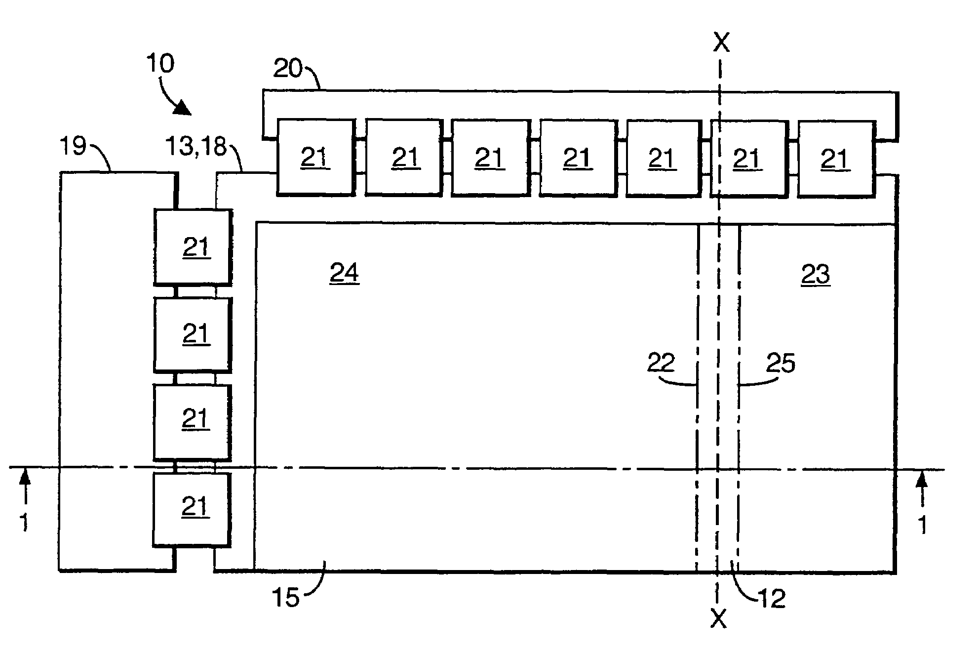
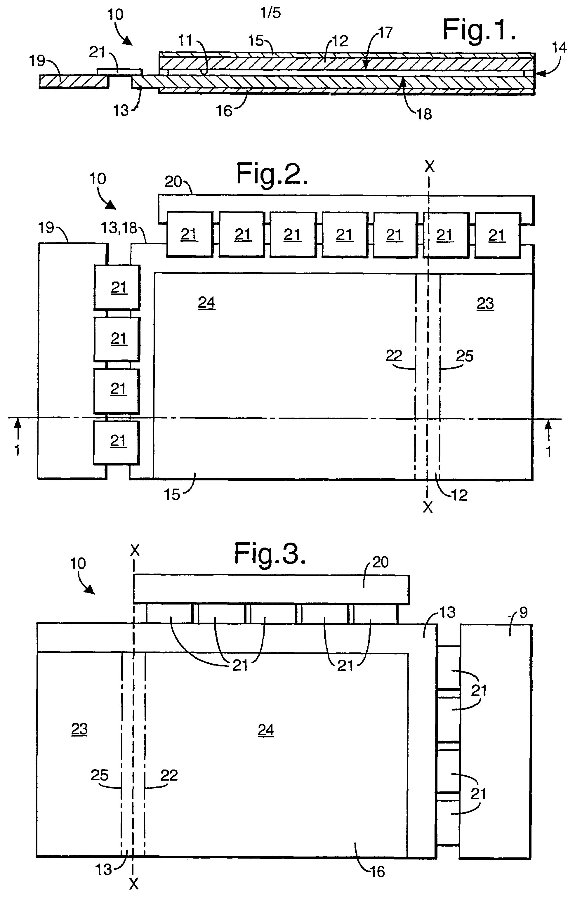
[0039]In a first embodiment, as will be seen from FIGS. 1 and 2, the glass plate 13 and its associated conductive layer 18 are larger than the glass plate 12 so that they extend to the left towards a vertical driver card 19, and upwards towards a horizontal driver card 20. A series of ribbon connectors or TABs 21 electrically interconnect the driver cards 19 and 20 with the various portions of the conductive layers 17 and 18 in well-known manner so that the driver cards 19, 20 will determine which portions of the conductive layers 17 and 18 are to be energized.

[0040]FIG. 3 shows the reverse side of the liquid crystal display 10, the reverse side of the vertical and horizontal TAB's 21, driver cards 19 and 20, and the light polarizing substrate 16.

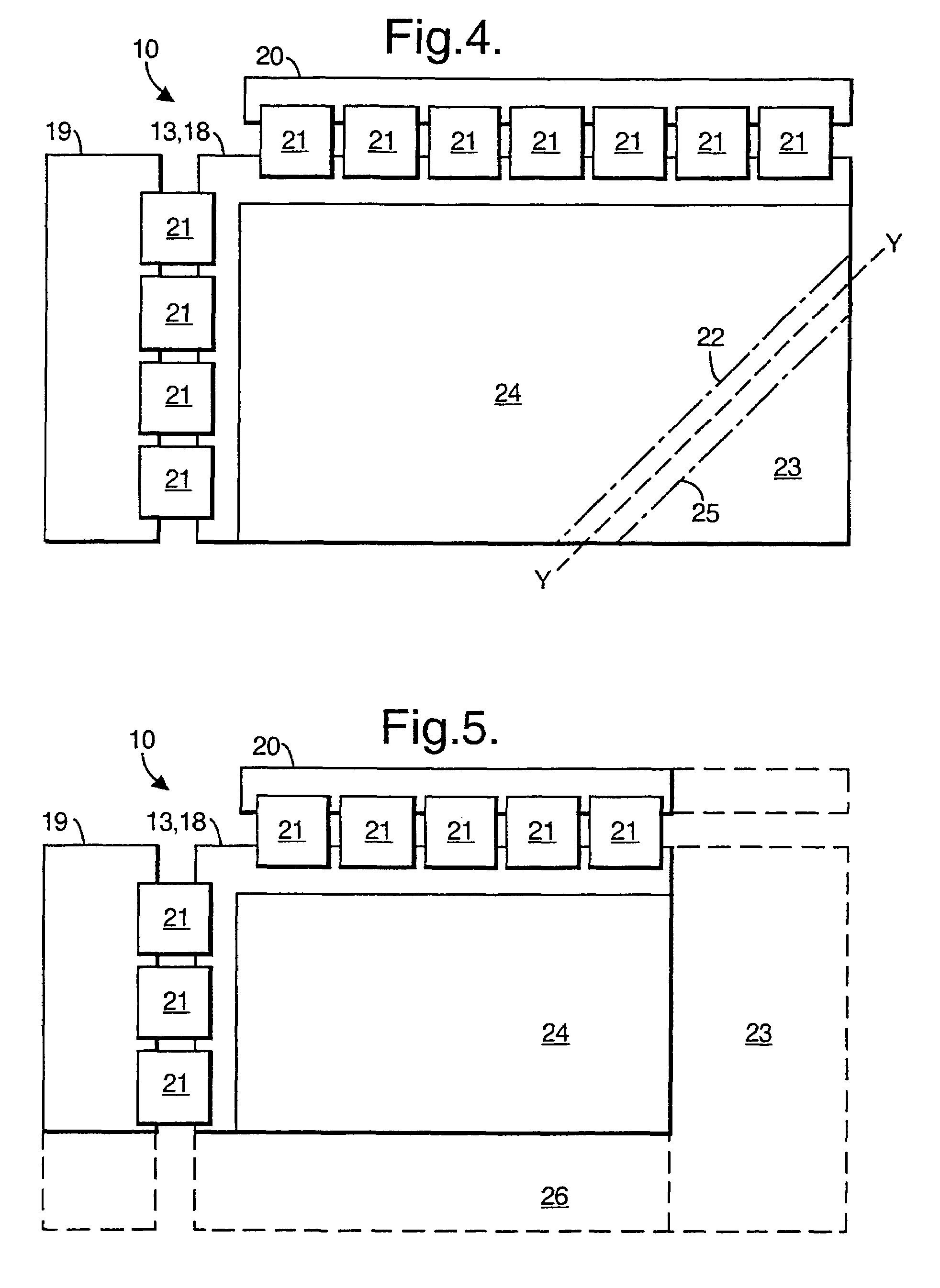
[0041]In FIGS. 2 and 3 the required width of the final liquid crystal display 10 is indicated by a chained line 22 and is achieved by removing an excess region 23 of the liquid crystal display 10 in the following manner. With reference to F...

second embodiment

[0054]FIGS. 6 and 7 illustrate the process for removing an excess region from a pre-manufactured liquid crystal display. The same reference numerals have been used as those in FIGS. 2 to 5 to denote equivalent features.

[0055]The required shape of the final liquid crystal display 10 is indicated by a solid line 22 and is achieved by removing an excess region 23 of the liquid crystal display 10 in the following manner.

[0056]With reference to FIG. 6, narrow strips of light polarizing substrate 15, 16, defined by the solid line 22 and a parallely-spaced line 25 on the opposite side of broken line C-C, are optionally removed from both sides of the liquid crystal display 10 and the exposed areas cleaned, as previously described. A laser, not shown, is then used to cut through glass plate 12 and glass plate 13 along line C-C. In this manner both glass plates 12, 13 are cut at the same time and the excess region 23 of the liquid crystal display 10 can be removed to expose cut edges of the g...

third embodiment

[0061]In the process, not illustrated, the liquid crystal within the liquid crystal display or a part thereof can be frozen or have its viscosity reduced using liquid nitrogen and both plates can then be machined through in one action using, for example, a diamond wheel cutter. In this manner the risk of contamination of the liquid crystal is mitigated and the number of voids introduced into the liquid crystal is reduced.

[0062]Should a liquid crystal display be required with a larger operative region then, as shown in FIG. 9, four liquid crystal displays 10 can be prepared as described with reference to FIG. 5 and can have their respective operative regions 24 combined by aligning and abutting their respective cut edges 27 and 28, the four liquid crystal displays 10 then being laminated to form a single display with increased operative area. Such lamination is preferably achieved by adhering transparent plates to the entire front and back surfaces of the four operative regions 24 us...


PUM

PropertyMeasurementUnit
physical shapeaaaaaaaaaa
dimensionsaaaaaaaaaa
areaaaaaaaaaaa

Abstract

A custom made liquid crystal display is formed from a pre-manufactured liquid crystal display by removing an excess region. The driver card is cut along the line X-X and the excess TABs are disconnected from the conductive layer. Optionally, a narrow strip is removed from each of the polarizing substrates between the lines to expose their associated glass plates. A groove is then cut into the exposed surface of each of the glass plates. Each glass plate is then fractured along the base of its groove so that the excess region is detached from the operative region. The cut edges of the glass plates are then sealed by applying a bead of ultra-violet curing adhesive. The processes of removing an excess region by cutting the glass plates with a laser or by freezing the liquid crystal between the glass-plates and machining through the glass plates are also described.

Description

BACKGROUND OF THE INVENTION[0001]This invention relates to a liquid crystal display, to a method of manufacturing a liquid crystal display, and also to apparatus to aid manufacture of a liquid crystal display.[0002]Generally, displays for reproduction of information have historically been of a cathode ray tube type construction. In an environment where space is limited traditional displays were typically manufactured to be square, or square with rounded corners, in order to make the best use of the limited space available.[0003]Liquid crystal displays are currently considered suitable substitutes for applications previously requiring cathode ray tube technology. The replacement of cathode ray tubes can be either for new applications or for the purpose of upgrading existing technology through retrofit design. When manufactured in large quantities, liquid crystal displays are of modest cost compared with an equivalent cathode ray tube.[0004]JP A 8146444 illustrates a typical method of...

Claims


Application Information

Patent Timeline
Patent Type & Authority Patents(United States)
IPC IPC(8): G02F1/1333C03B33/033C03B33/07
CPCB32B17/06C03B33/033C03B33/04C03B33/076G02F1/133351C03B33/074G02F1/13336
Inventor WATSON, DAVID S
Owner BAE SYSTEMS PLC
Why Eureka
Try Eureka