Apparatus and method for retroactively installing sensors on marine elements

a technology of retroactive installation and monitoring system, applied in the field of apparatus and methods for monitoring, can solve problems such as interference, subsea equipment, and pipe internal and external walls that are easily damaged

Inactive Publication Date: 2008-07-15
SHELL OIL CO
View PDF60 Cites 80 Cited by
  • Summary
  • Abstract
  • Description
  • Claims
  • Application Information

AI Technical Summary

Benefits of technology

[0011]The present invention contemplates that the fiber optic sensors and their umbilicals are secured to the collars or other support structures. The support structure is then deployed subsea and installed on an existing subsea structure. The umbilicals may be removably attached to the support structure. This permits subsequent replacement of a sensor / umbilical in the event of failure. Alternatively, it permits installation of the sensor / umbilical following attachment of the support structure to the structure. In the present invention, multiple sensor / umbilical pairs may be attached to a single support structure. When the support structure is attached to the subsea structure, the sensors are fixed in position relative to the subsea structure. It will be appreciated that multiple support structures / umbilical / sensor assemblies may be attached to the subsea structure, thereby permitting strain monitoring along the length of the subsea structure. The flexibility of support structure design and attachment scheme of the sensor / umbilical pairs permits the user to design a custom monitoring system for the subsea structure.

Problems solved by technology

As the light is reflected, part of the light is transmitted each time it reaches the surface, resulting in multiple offset beams that set up an interference.
As the slugs pass through a pipeline, the internal pressure within the pipe increases, resulting in detectable strain in the pipe internal and external walls.
It will be appreciated that the failure of a piece of subsea equipment due to temperature failure would have a disastrous effect on the environment.

Method used


Image

  • Apparatus and method for retroactively installing sensors on marine elements
  • Apparatus and method for retroactively installing sensors on marine elements
  • Apparatus and method for retroactively installing sensors on marine elements

Examples


Embodiment Construction

[0029]In one embodiment the structure to which the monitoring system is attached is discussed in terms of a tubular subsea element. However, it will be appreciated that the structure need not be tubular. The specific geometry of the support structure and the means of securing it about the structure may be readily varied to the geometry of the structure. Moreover, the structure need not be limited to a subsea element, as the same principles would operate with a horizontal or vertical structure, subsea or on the land.

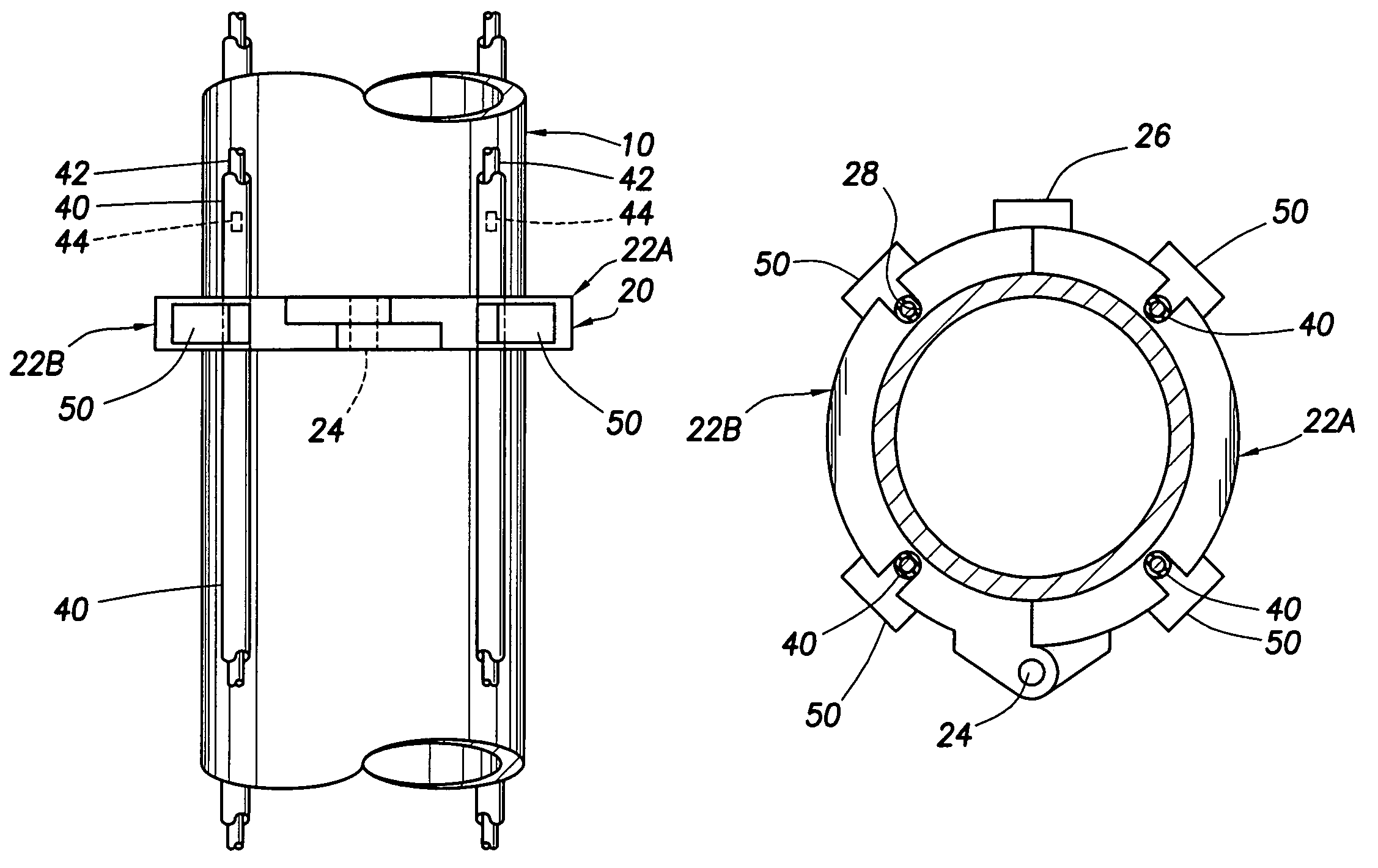
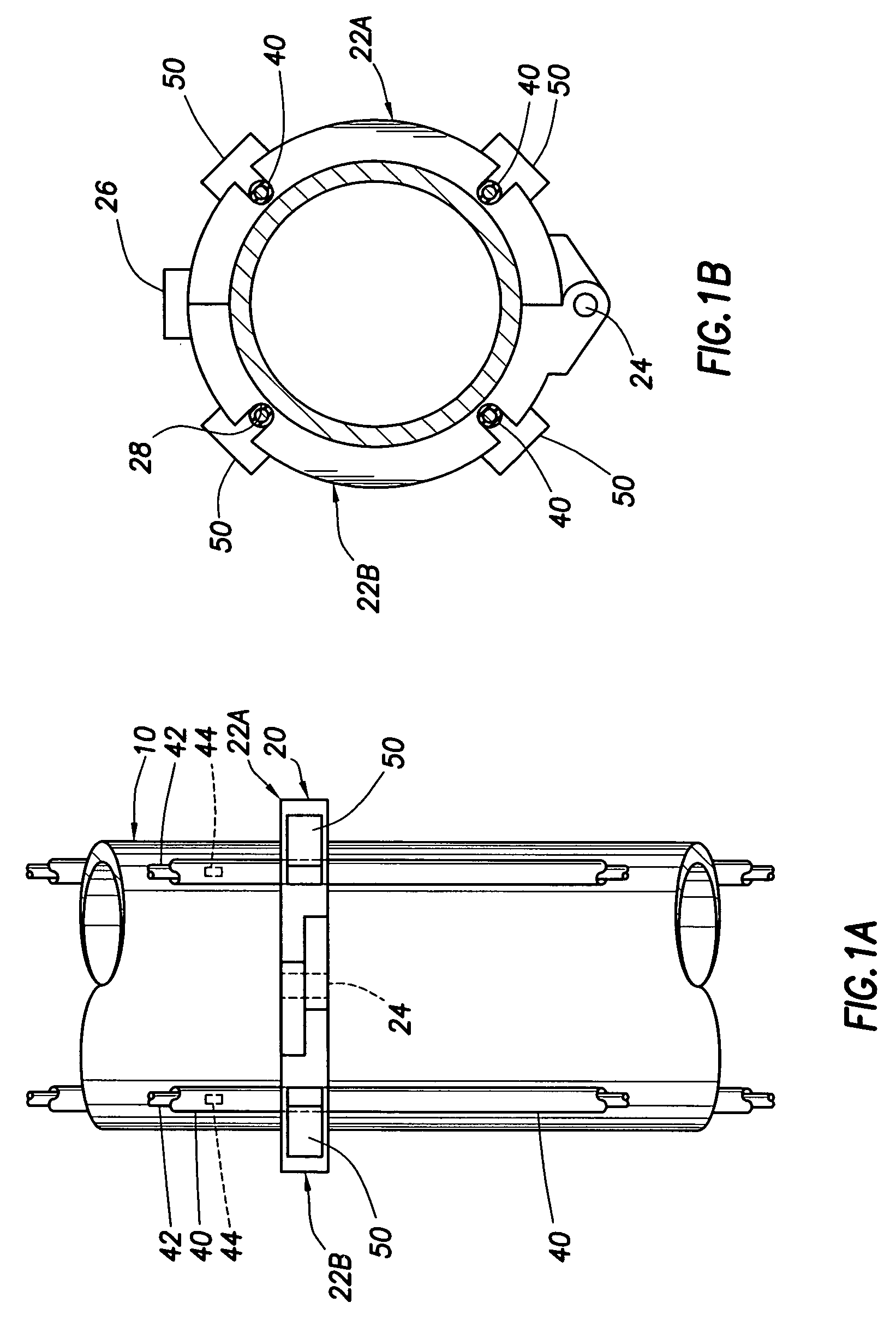
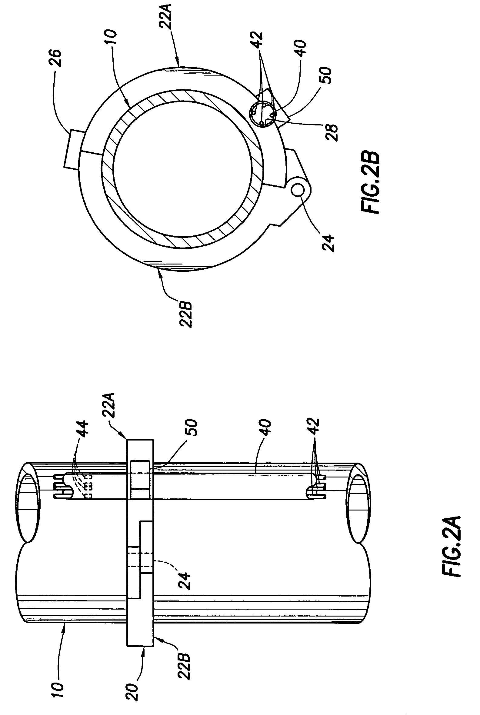
[0030]In FIGS. 1A and 1B, a cutaway of a subsea element 10 is shown with one embodiment of the monitoring system of the present invention mounted thereon. A collar 20 is shown comprised of two collar sections 22A and 22B. The collar sections 22A and 22B each have a hinge portion built therein and are pinned together by pin 24, thus allowing the collar sections 22A and 22B to open and close tightly about the vertical element 10. It will be appreciated that a deformable mat...


PUM

PropertyMeasurementUnit
temperaturesaaaaaaaaaa
physicalaaaaaaaaaa
transmissionaaaaaaaaaa

Abstract

Sensors, including fiber optic sensors and their umbilicals, are mounted on support structures designed to be retro-fitted to in-place structures, including subsea structures. The sensor support structures are designed to monitor structure conditions, including strain, temperature, and in the instance of pipelines, the existence of production slugs. Moreover the support structures are designed for installation in harsh environments, such as deep water conditions using remotely operated vehicles.

Description

RELATED APPLICATIONS[0001]This application claims priority to the provisional application having Ser. No. 60 / 624,736, which was filed on Nov. 3, 2004. The provisional application having Ser. No. 60 / 624,736 is herein incorporated by reference in its entirety.[0002]The application is also related to the subject matter disclosed in U.S. application Ser. No. 10 / 228,385, filed 26 Aug. 2002, the subject matter of which is herein incorporated by reference.FIELD OF THE INVENTION[0003]The present invention relates to apparatus and methods for monitoring fatigue, structural response and operational limits in structural components. More particularly the present invention relates to apparatus and methods for installation of monitoring systems on marine and land structural members.DESCRIPTION OF THE RELATED ART[0004]All structures respond in some way to loading, either in compression, tension, or combinations of various loading modes. While most structures and systems are designed to accommodate...

Claims


Application Information

Patent Timeline
Patent Type & Authority Patents(United States)
IPC IPC(8): G01L1/24
CPCE21B17/01E21B47/01E21B47/0006E21B47/0001E21B47/001E21B47/007G01L1/246
Inventor ALLEN, DONALD WAYNEMCMILLAN, DAVID WAYNE
Owner SHELL OIL CO
Why Eureka
Try Eureka