
Automated teller machine system and method relay center

a technology relay center, which is applied in the field of automatic teller machine (atm), can solve the problems of not necessarily providing cash money in settlement processing, and achieve the effect of enabling smooth settlement processing performan

Inactive Publication Date: 2008-07-15
BANK OF TOKYO MITSUBISHI BTM
View PDF21 Cites 3 Cited by
  • Summary
  • Abstract
  • Description
  • Claims
  • Application Information

AI Technical Summary

Benefits of technology

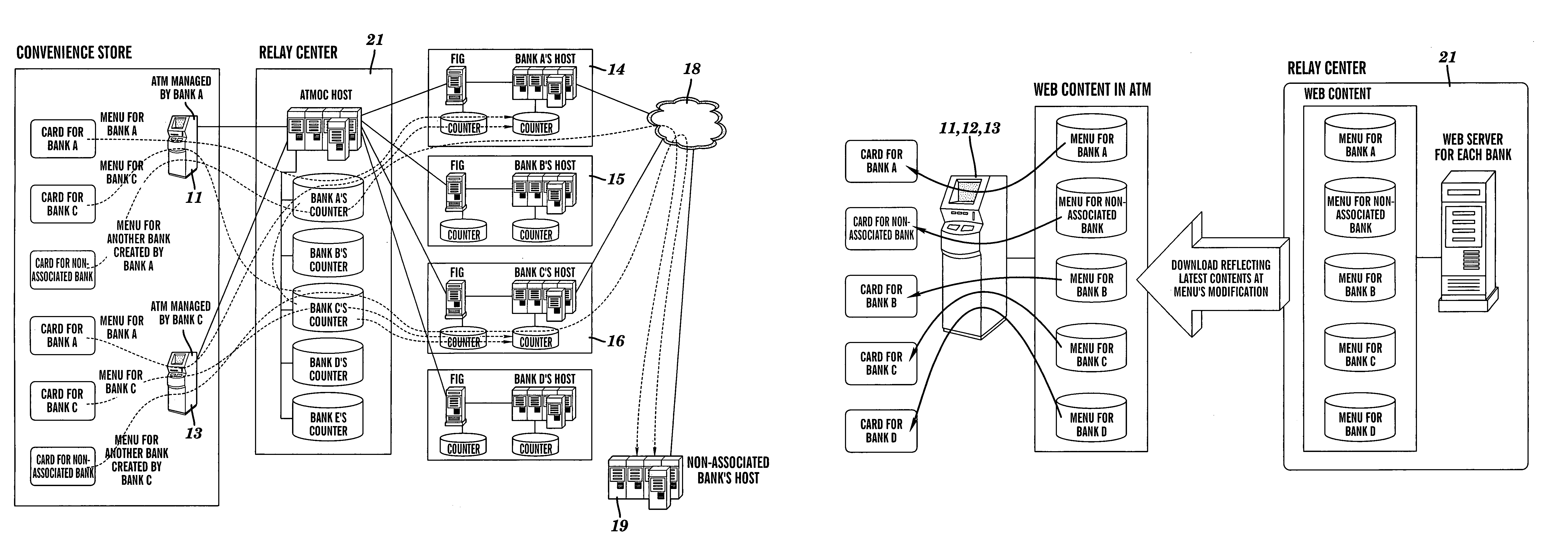
[0012]The method may be characterized in that a counter provided in the relay center for each associated financial institution separately is updated based on the transaction request message or the transaction response message. This feature is desirable in that it allows accumulation of transaction information of each associated financial institution in the relay center, thereby simplifying settlement processing. More particularly, if a counter is updated based on the transaction response message transmitted from an associated financial institution, it is possible to accumulate the transaction information based on a transaction content associated with a defined amount of withdrawal or the like, thereby increasing credibility.
[0015]The method may further provide that after this financial institution is identified, a menu screen previously stored in the automated teller machine is displayed on the display as an initial transaction menu, and one or more succeeding menu screens received from a remote location are displayed on the display. According to such an arrangement, it is possible to eliminate time required for communicating the initial transaction menu before its display, thereby enabling immediate actions to be performed. This feature is advantageous in that there is no need for this automated teller machine to have all of the menu contents and, thus, it has no need to have a large memory capacity.
[0018]The system may be further characterized in that the identified financial institution system updates counters provided therein based on the transaction request messages or the transaction response messages, and that the relay center updates counters provided therein based on the transaction request messages or the transaction response messages. The system may be further characterized in that the relay center defines a settlement amount after exchanging information of the counters provided in the identified financial institution systems and the counters provided in the relay center. The system may be further characterized in that the automated teller machine is managed by a particular financial institution, and that a settlement with the relay center is performed by the particular financial institution or a selected financial institution other than the particular financial institution. If the settlement is performed by the selected financial institution, that financial institution performs a settlement with another financial institution. With these arrangements, a settlement of each financial institution may be centralized at the relay center, thereby enabling smooth settlement processing performance.
[0019]This invention is also directed to a system of using an automated teller machine, which comprises: an automated teller machine for identifying a financial institution based on an account identifying medium to conduct a financial transaction with a customer; a plurality of financial institution systems for conducting transactions with this automated teller machine; and a relay center for relaying transactions between the automated teller machine and the financial institution systems; wherein the automated teller machine enciphers a personal identification number inputted by the customer and transmits the enciphered personal identification number to the relay center for use in the identified financial institution, wherein the relay center transmits the enciphered personal identification number to the identified financial institution system, and wherein the identified financial institution system deciphers the enciphered personal identification number. More particularly, this invention is characterized in that this financial institution system has a private key and a public key, that the automated teller machine receives the public key from the financial institution system through the relay center, and enciphers the personal identification number using a public key which is different for each financial institution, and that the financial institution system uses the private key for deciphering the personal identification number enciphered by the public key. With these arrangements, each bank's center alone having a private key is capable of deciphering. Thus, it is possible to overcome the problems such as exposure of a personal identification number on line and / or at the relay center.

Problems solved by technology

Note, however, that it does not necessarily deliver cash money in terms of settlement processing to be described below.

Method used


Image

  • Automated teller machine system and method relay center
  • Automated teller machine system and method relay center
  • Automated teller machine system and method relay center

Examples


Embodiment Construction

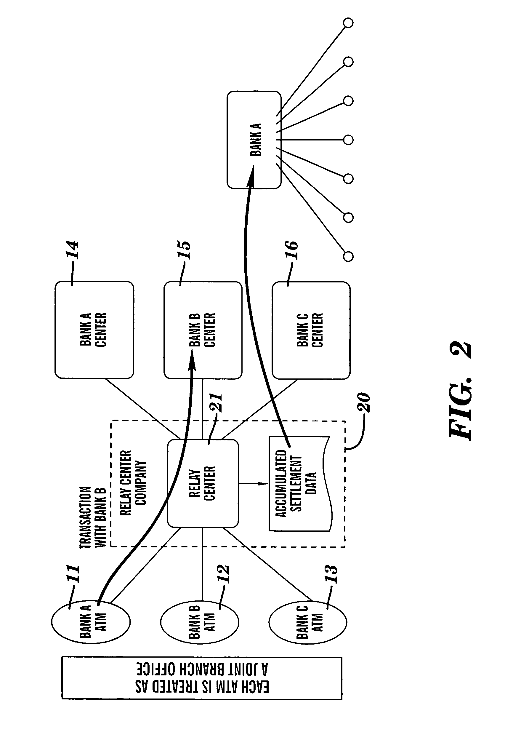
[0037]FIG. 2 is a pictorial representation illustrating a system configuration of a preferred embodiment of the present invention. The embodiment is configured such that automated teller machines 11, 12, 13 (ATMs) and center systems of financial institutions such as banks 14, 15, 16 (hereafter simply called “centers”) are dissociated from each other, and that a relay center 21 of a relay center company 20 is caused to intervene between them. More particularly, Bank A's ATM 11, Bank B's ATM 12 and Bank C's ATM 13 are connected to Bank A's center 14, Bank B's center 15 and Bank C's center 16, respectively, through relay center 21. Relay center 21 is managed by relay center company 20. Notations of Bank A's ATM 11, Bank B's ATM 12 and Bank C's ATM 13 mean that Bank A, Bank B and Bank C are responsible for managing these ATMs, which may be installed by relay center company 20. These notations do not necessarily mean that these ATMs are installed at the respective banks. For example, the...


PUM


Abstract

Automated teller machine systems and methods for reducing system development efforts by financial institutions and for providing a financial transaction system that is adapted for using one or more common ATMs. In addition, systems and methods to simplify settlement processing of transactions based on ATMs of each financial institution. ATMs and center systems of financial institutions are dissociated from each other, and a relay center intervenes between them.

Description

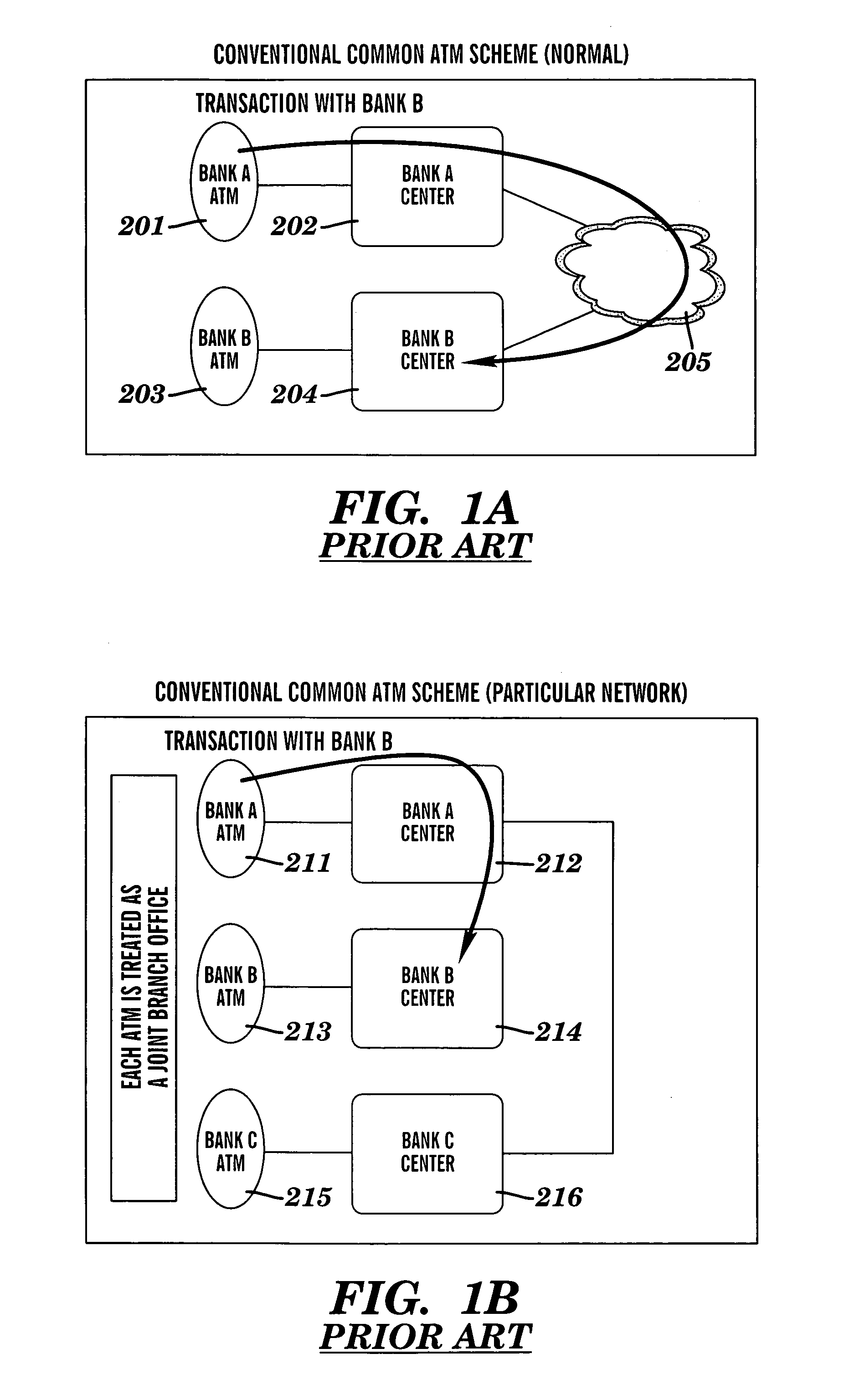
BACKGROUND OF THE INVENTION[0001]1. Field of the Invention[0002]This invention relates to an automated teller machine (ATM) of a financial institution and, more particularly, to a financial system or the like for providing financial services by using a common ATM.[0003]2. Related Art[0004]For a retail transaction (petty financial transaction) in a financial institution, a cash dispenser (CD) and / or an automated teller machine (ATM) have been used over the years to automate a withdrawal and / or a deposit of cash. In this specification, these machines are collectively called an “ATM” or “automated teller machine”. In a transaction using an ATM, such as the one that uses an ATM at a particular bank to withdraw a deposit from an account at another bank, it is normally necessary to pay a predetermined service charge, which results in insufficient service to the customer. Thus, there has been proposed a common ATM scheme, which makes a service charge among the involved financial institutio...

Claims


Application Information

Patent Timeline
IPC IPC(8): G06Q40/00G07D9/00G06Q40/02G07F19/00
CPCG06Q20/10G06Q20/102G06Q20/105G06Q20/108G07F19/211G06Q20/202G06Q20/40G07F19/20G06Q20/1085
Inventor MIYAZAKI, MASAKIHASEGAWA, AKIRA
Owner BANK OF TOKYO MITSUBISHI BTM
Learn More