Wire cutting/tying tool

a wire cutting/tying tool and hand-operated technology, applied in the field of tools, can solve the problems of time-consuming process, and achieve the effect of improving efficiency during construction operations

Inactive Publication Date: 2008-07-22
BUCH KEVIN
View PDF15 Cites 5 Cited by
  • Summary
  • Abstract
  • Description
  • Claims
  • Application Information

AI Technical Summary

Benefits of technology

[0010]In view of the foregoing background, it is therefore an object of the present invention to provide a wire cutting / tying tool. These and other objects, features, and advantages of the invention are provided by a hand-operated wire cutting and tying tool for improving efficiency during construction operations.

Problems solved by technology

This is a time-consuming process when done with two separate tools for tying and cutting the wire, as is the conventional practice.

Method used


Image

  • Wire cutting/tying tool
  • Wire cutting/tying tool
  • Wire cutting/tying tool

Examples


Embodiment Construction

[0022]The present invention will now be described more fully hereinafter with reference to the accompanying drawings, in which a preferred embodiment of the invention is shown. This invention may, however, be embodied in many different forms and should not be construed as limited to the embodiment set forth herein. Rather, this embodiment is provided so that this application will be thorough and complete, and will fully convey the true scope of the invention to those skilled in the art. Like numbers refer to like elements throughout the figures.

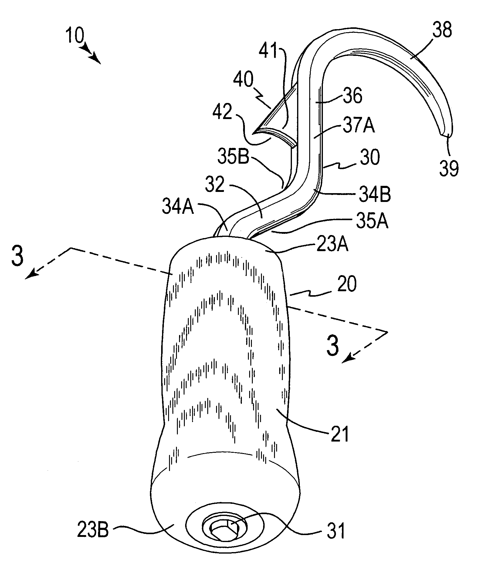
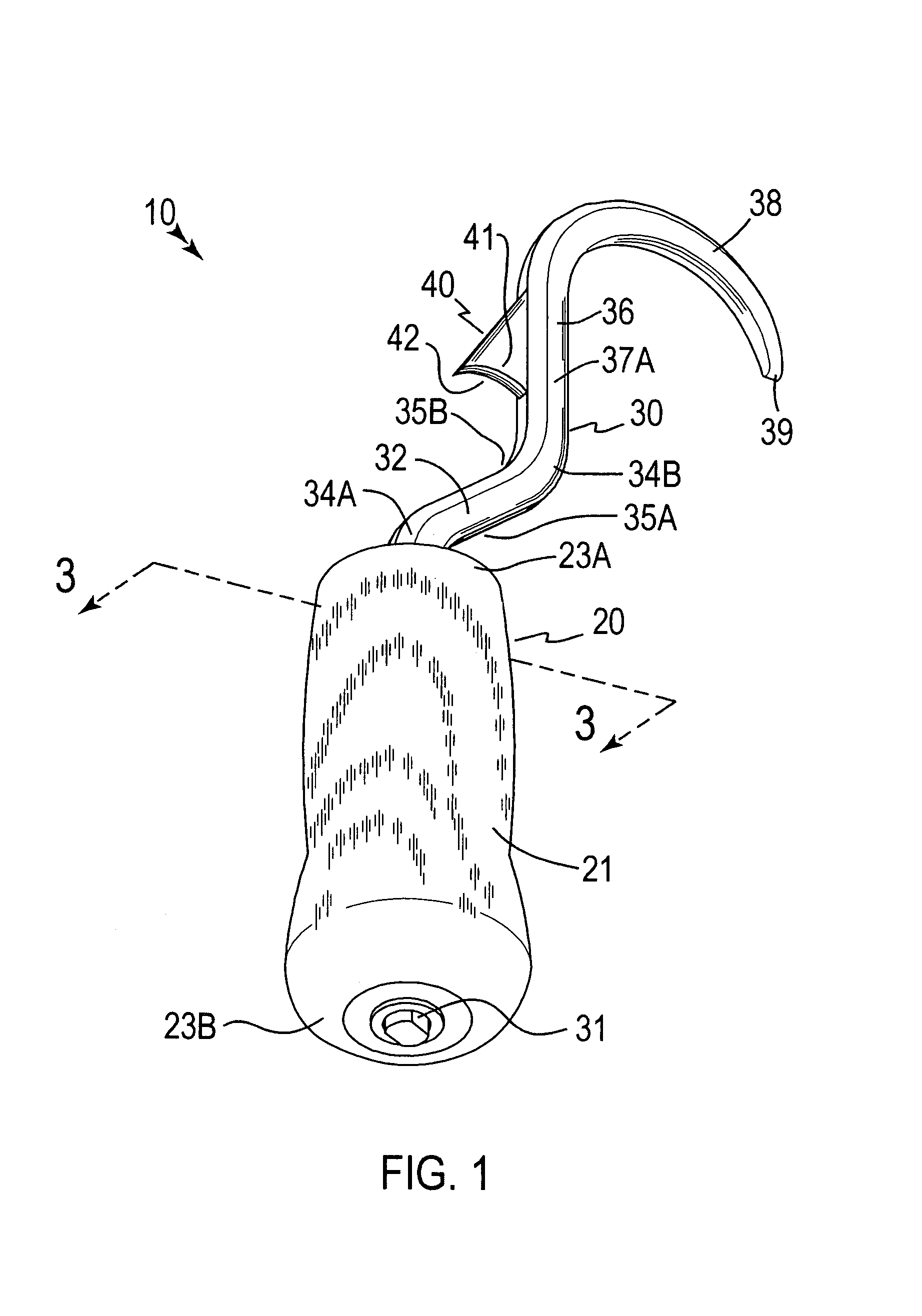
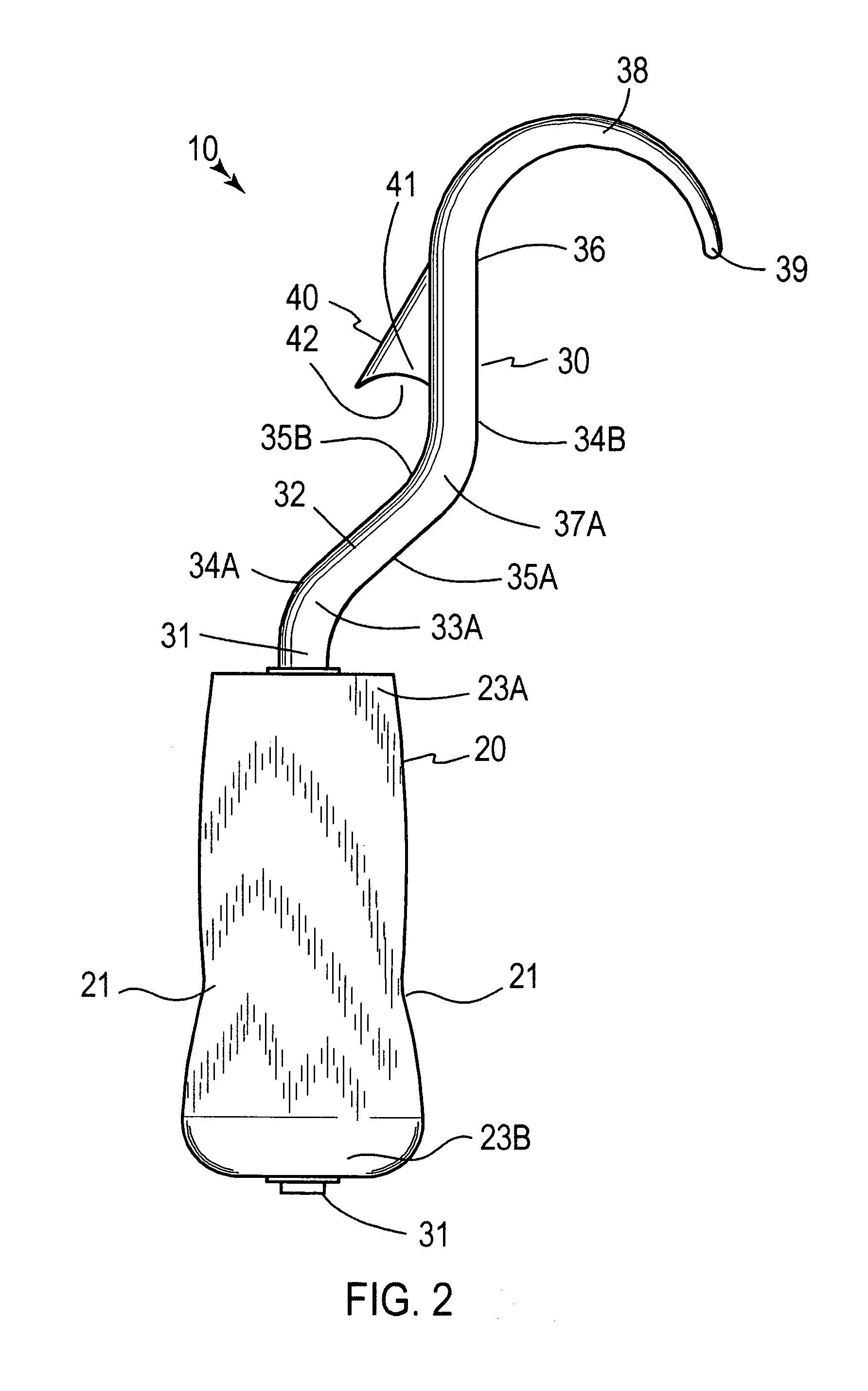
[0023]The apparatus of this invention is referred to generally in FIGS. 1-3 by the reference numeral 10 and is intended to provide a wire cutting / tying tool. It should be understood that the apparatus 10 may be used to cut and tie many different types of wires and should not be limited in use to only rebar wire tying and cutting applications.

[0024]Referring initially to FIGS. 1, 2 and 3, the apparatus 10 includes a wooden handle 20 that has a...


PUM


Abstract

A tool includes a wooden handle that has a curvilinear outer surface extending along an entire length thereof. The handle has a centrally registered axial bore formed therein that travels between distal and proximal ends of the handle such that the bore passes through the entire length thereof. An elongated swivel arm has an overall length greater than the handle length and is rotatably coupled to the handle such that same freely rotates along clockwise and counter clockwise directions. A cutting blade is monolithically formed with the swivel arm, is distally spaced from the handle, and is axially offset from a centrally registered longitudinal axis of the handle. The cutting blade rotates in sync with the swivel arm and has a concave face. The cutting blade is proximally spaced from a distal end of the swivel arm.

Description

CROSS REFERENCE TO RELATED APPLICATIONS[0001]This application claims the benefit of U.S. Provisional Application No. 60 / 682,312, filed May 19, 2005.STATEMENT REGARDING FEDERALLY SPONSORED RESEARCH OR DEVELOPMENT[0002]Not Applicable.REFERENCE TO A MICROFICHE APPENDIX[0003]Not Applicable.BACKGROUND OF THE INVENTION[0004]1. Technical Field[0005]This invention relates to tools and, more particularly, to a hand-operated wire cutting / tying tool for improving efficiency during construction operations.[0006]2. Prior Art[0007]Concrete is a commonly used building material. Forms are fashioned and concrete is poured into the forms to harden, and then the forms are removed. To reinforce the concrete, a grid of metal “rebar” rods may be placed within the forms so that when the concrete hardens, it is strengthened by the rebar. The grid can be formed by a set of horizontal rebar rods which intersects with a set of vertical rebar rods. To hold the rebar grid in place, it is common to tie off the c...

Claims


Application Information

Patent Timeline
Patent Type & Authority Patents(United States)
IPC IPC(8): B26B3/00
CPCB26B1/02B26B11/006E04G21/122
Inventor BUCH, KEVIN
Owner BUCH KEVIN
Why Eureka
Try Eureka