X-ray apparatus with component positioning coordinated with radio-opaque objects in examination room

a technology of x-ray apparatus and radio-opaque objects, which is applied in the direction of radiation beam directing means, applications, instruments, etc., can solve the problems of incorrect (flawed) exposure, increased time expenditure, and inability to always reliably be possible, so as to achieve the effect of shortening the tim

Inactive Publication Date: 2008-07-22
SIEMENS HEALTHCARE GMBH
View PDF3 Cites 36 Cited by
  • Summary
  • Abstract
  • Description
  • Claims
  • Application Information

AI Technical Summary

Benefits of technology

[0005]An object of the present invention is to provide an x-ray acquisition apparatus of the aforementioned type in which the desired x-ray imaging (data acquisition) result can be completed in a shorter amount of time.
[0008]By means of the signal that is emitted as an output from the control unit when a radio-opaque object is located in the beam path, the user is presented in a simple manner with the possibility to change the position of the x-ray detector before an x-ray acquisition is initiated. Incorrect exposures due to radio-opaque objects that are located in the beam path are thereby reliably avoided and the desired x-ray imaging result can be acquired in a shorter amount of time.
[0012]The use of further sensors that are attached to the radio-opaque objects is advantageous. The positions of the radio-opaque objects are determined via these sensors and transmitted to the control unit. The position of movable radio-opaque objects during movement thereof thus can also be taken into account.
[0013]In a preferred embodiment of the invention, the x-ray acquisition apparatus has a collimator that is controllable via the control unit such that the radiation field of the x-ray source is limited and matched to the size of the x-ray detector. The manual set-up step in which the collimator is adjusted is thus omitted. The acquisition can be executed without time delay.
[0015]The mounting device on which x-ray source is mounted preferably is equipped with a collision detection system so that collisions with objects or people are avoided during movement of the x-ray source towards the x-ray detector.
[0018]The mounting device of the x-ray source and / or of the x-ray detector can be a robot arm with six degrees of freedom. Such a robot allows a large freedom of movement with a space-saving design.

Problems solved by technology

This assessment represents an additional time expenditure and is not always reliably possible, so that incorrect (flawed) exposures can be created.

Method used


Image

  • X-ray apparatus with component positioning coordinated with radio-opaque objects in examination room
  • X-ray apparatus with component positioning coordinated with radio-opaque objects in examination room

Examples


Embodiment Construction

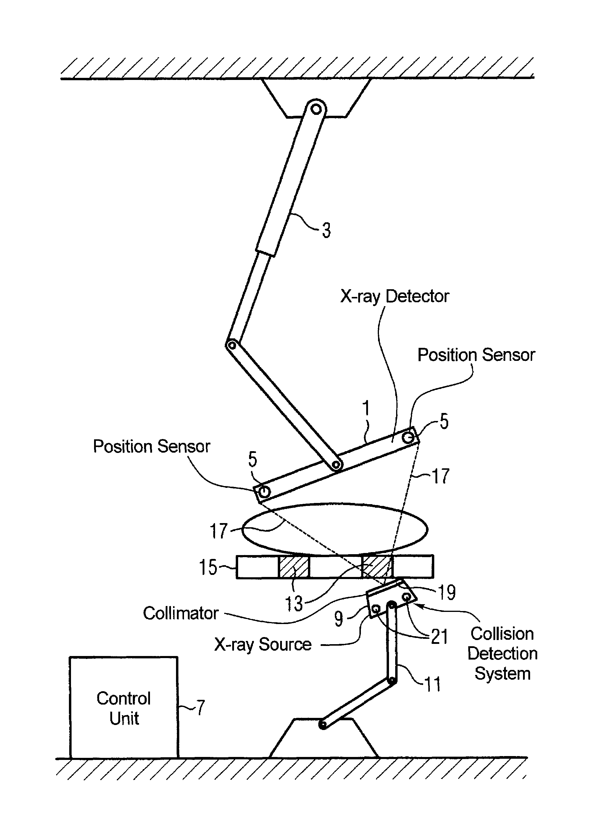
[0020]The drawing shows a ceiling-mounted x-ray detector 1 that can be three-dimensionally adjusted in space with a manually adjustable mounting arm 3 with six degrees of freedom. Sensors 5 are located on the x-ray detector 1 that supply signals to a control unit 7 that calculates therefrom the spatial position of the x-ray detector 1. An x-ray source 9 is adjustable in a motorized manner in space by a robot arm 11 with six degrees of freedom and is aligned relative to the x-ray detector 1 by control signals from the control unit 7. The spatial positions of radio-opaque objects such as, for example, radio-opaque parts 13 of the operating table 15 are stored in the control unit 7. If a radio-opaque object 13 is located in the beam path 17 (as is shown in the drawing), a signal that informs the user about this situation is output by the control unit 7. The user can thereupon reposition the x-ray detector 1.

[0021]A collimator 19 is located on the x-ray source 9 that is automatically co...


PUM


Abstract

An x-ray acquisition apparatus has a spatially adjustable x-ray detector, a spatially adjustable x-ray source, and a control unit with which the x-ray source can be aligned relative to the x-ray detector. The control unit accounts for the position of radio-opaque objects in the examination room and, before an x-ray acquisition, outputs a signal is a radio-opaque object is located in the beam path of the x-ray source.

Description

BACKGROUND OF THE INVENTION[0001]1. Field of the Invention[0002]The present invention concerns an x-ray acquisition apparatus of the type having a spatially adjustable x-ray detector, a spatially adjustable x-ray source, and a control unit with which the x-ray source can be aligned to the x-ray detector.[0003]2. Description of the Prior Art[0004]An x-ray acquisition apparatus of this type is known from DE 196 11 705 B4. In the x-ray acquisition apparatus described there, the x-ray source can be aligned relative to the x-ray detector that can be adjusted three-dimensionally in space. This known x-ray acquisition apparatus does not take into account the position of radio-opaque objects that are located in the room (such as perhaps a patient bed that may be located in the beam path). After every positioning of the x-ray detector, therefore, the user must ascertain whether a radio-opaque object is located in the beam path. This assessment represents an additional time expenditure and is...

Claims


Application Information

Patent Timeline
Patent Type & Authority Patents(United States)
IPC IPC(8): A61B6/12
CPCA61B6/4441A61B6/4476A61B6/4464A61B6/588A61B6/4452A61B6/4458A61B6/587A61B6/102
Inventor GRAUMANN, RAINERRITTER, DIETER
Owner SIEMENS HEALTHCARE GMBH
Why Eureka
Try Eureka