Turbine exhaust strut airfoil profile

a technology of exhaust strut and airfoil, which is applied in the manufacture of engines, reaction engines, machines/engines, etc., can solve the problems of undesirable tangential velocity components of hot combustion gases, and achieve the effects of reducing manufacturing tolerance, preventing the process of flow separation, and being more tolerant to manufacturing toleran

Active Publication Date: 2008-07-22
PRATT & WHITNEY CANADA CORP
View PDF5 Cites 64 Cited by
  • Summary
  • Abstract
  • Description
  • Claims
  • Application Information

AI Technical Summary

Benefits of technology

[0010]This design profile advantageously removes large amounts of residual swirl which exits the LP turbine. The unique airfoil shape is more tolerant to manufacturing tolerance, and can handle a wide variety of engine operating conditions. As well, the airfoil length varies between the inner to the outer annulus walls in order to impede the process of flow separation. The airfoil is adapted to fabrication by wrapping sheet metal into the strut shape. Such a fabrication, while being low cost and low weight, exposes the design to a larger tolerance range. In spite of this larger tolerance range, the airfoil shape still meets all of its requirements.

Problems solved by technology

The tangential velocity component of the hot combustion gases is undesirable as it detracts from the momentum increase that produces a forward axial thrust in the gas turbine engine.

Method used


Image

  • Turbine exhaust strut airfoil profile
  • Turbine exhaust strut airfoil profile
  • Turbine exhaust strut airfoil profile

Examples


Embodiment Construction

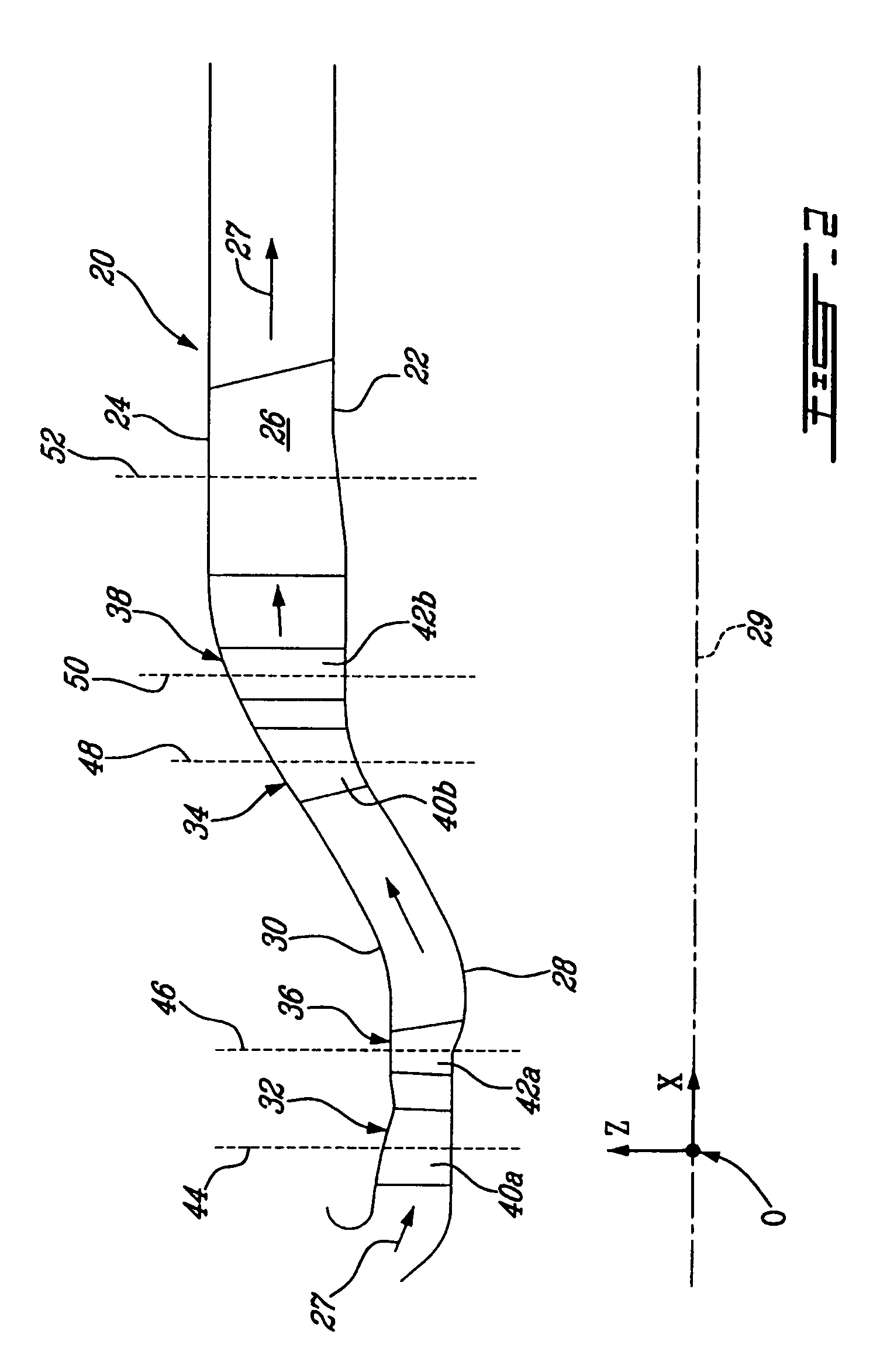
_n">[0015]FIG. 3 is a schematic elevation view of an exhaust strut having an airfoil profile defined in accordance with an embodiment of the present invention; and

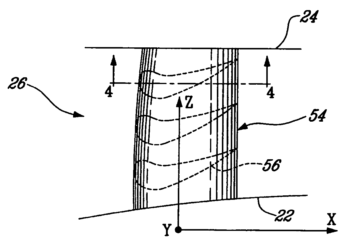
[0016]FIG. 4 is a cross-sectional view taken along lines 4-4 of FIG. 3, showing a representative profile section of the airfoil portion of the strut.

DETAILED DESCRIPTION OF THE PREFERRED EMBODIMENTS

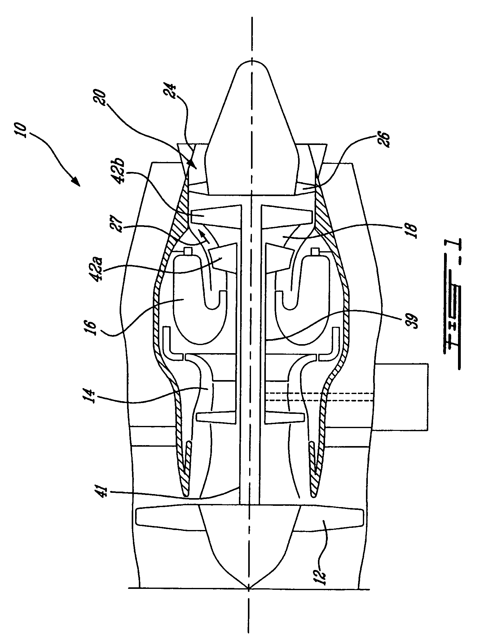
[0017]FIG. 1 illustrates a gas turbine engine 10 of a type preferably provided for use in subsonic flight, generally comprising in serial flow communication a fan 12 through which ambient air is propelled, a multistage compressor 14 for pressurizing the air, a combustor 16 in which the compressed air is mixed with fuel and ignited for generating an annular stream of hot combustion gases, and a turbine section 18 for extracting energy from the combustion gases to drive the fan, the compressor, and produce thrust.

[0018]The gas turbine engine 10 further includes a turbine exhaust duct 20 which is exemplified as including an annular...


PUM


Abstract

A turbine exhaust thin strut includes an airfoil section having a profile substantially in accordance with at least an intermediate portion of the Cartesian coordinate values of X, Y and Z set forth in Table 2. The X and Y values are distances, which when smoothly connected by an appropriate continuing curve, define airfoil profile sections at each distance Z. The profile sections at each distance Z are joined smoothly to one another to form a complete airfoil shape.

Description

TECHNICAL FIELD[0001]The invention relates generally to an exhaust strut for a gas turbine engine and, more particularly, to an airfoil profile suited for the thin exhaust strut.BACKGROUND OF THE ART[0002]A gas turbine engine typically includes an exhaust duct through which hot combustion gases are flowed during operation of the engine. The exhaust duct conventionally comprises an inner cylindrical member forming the inner wall of the gaspath and an outer cylindrical member forming the outer wall of the gaspath. A plurality of radially extending struts spans the gaspath between the inner and outer cylindrical members.[0003]Hot combustion gases discharging from the turbine into the exhaust duct during operation of the engine have a residual velocity component in the tangential direction with respect to the inner annular gaspath. The tangential velocity component of the hot combustion gases is undesirable as it detracts from the momentum increase that produces a forward axial thrust i...

Claims


Application Information

Patent Timeline
Patent Type & Authority Patents(United States)
IPC IPC(8): F01D9/00
CPCF01D9/06F01D9/065F05D2250/74
Inventor GIRGIS, SAMIMOHAN, KRISHANEL-FOULY, MONA
Owner PRATT & WHITNEY CANADA CORP
Why Eureka
Try Eureka