Chemical feeder

Inactive Publication Date: 2005-07-07
INNOVATIVE WATER CARE LLC
View PDF40 Cites 7 Cited by
  • Summary
  • Abstract
  • Description
  • Claims
  • Application Information

AI Technical Summary

Benefits of technology

[0009] One aspect of the present invention is a feeder device for introducing one or more chemicals to a fluid comprising a housing having an inlet through which the fluid flows into the feeder device at an inlet flow rate and an outlet through which the fluid flows out of the feeder device at an outlet flow rate, a hopper having sidewalls and at least an open bottom, said hopper defining a top portion of said housing, a grid at least partially closing said open bottom, said grid having a top surface and a bottom surface, said grid and said hopper adapted to hold the one or more chemicals so that the one or more chemicals are supported by said top surface and are contained by said hopper sidewalls, a dissolving cup at least partially containing said hopper and said bottom surface of said grid, said dissolving cup having a bottom surface and sidewalls joined thereto, said sidewalls extending upwardly above said top surface of said grid, said bottom surface including a center nozzle in fluid communication with said inlet and oriented vertically toward said grid, said bottom surface positioned a predetermined distance from said top surface of said grid, said sidewalls having an opening formed therein, said opening having a predetermined cross-sectional area, a spout fluidly connected with said opening, said spout defining a horizontal channel having channel walls and a channel floor, said channel floor positioned a predetermined distance above said bottom surface of said dissolving cup, and an outlet chamber in fluid communication with said spout and said outlet, said outlet chamber defining a bottom portion of said housing.
[0010] Another aspect of the present invention is a feeder device for introducing one or more chemicals to a fluid comprising a housing having an inlet through which the fluid flows into the feeder device at an inlet flow rate and an outlet through which the fluid flows out of the feeder device at an outlet flow rate, a hopper having sidewalls and at least an open bottom, said hopper defining a top portion of said housing, a grid at least partially closing said open bottom, said grid having a top surface and a bottom surface, said grid and said hopper adapted to hold the one or m

Problems solved by technology

Obtaining proper dissolution of the treatment chemical and avoiding undesirable deposits or residues have posed problems in feeder

Method used


Image

  • Chemical feeder
  • Chemical feeder
  • Chemical feeder

Examples


Embodiment Construction

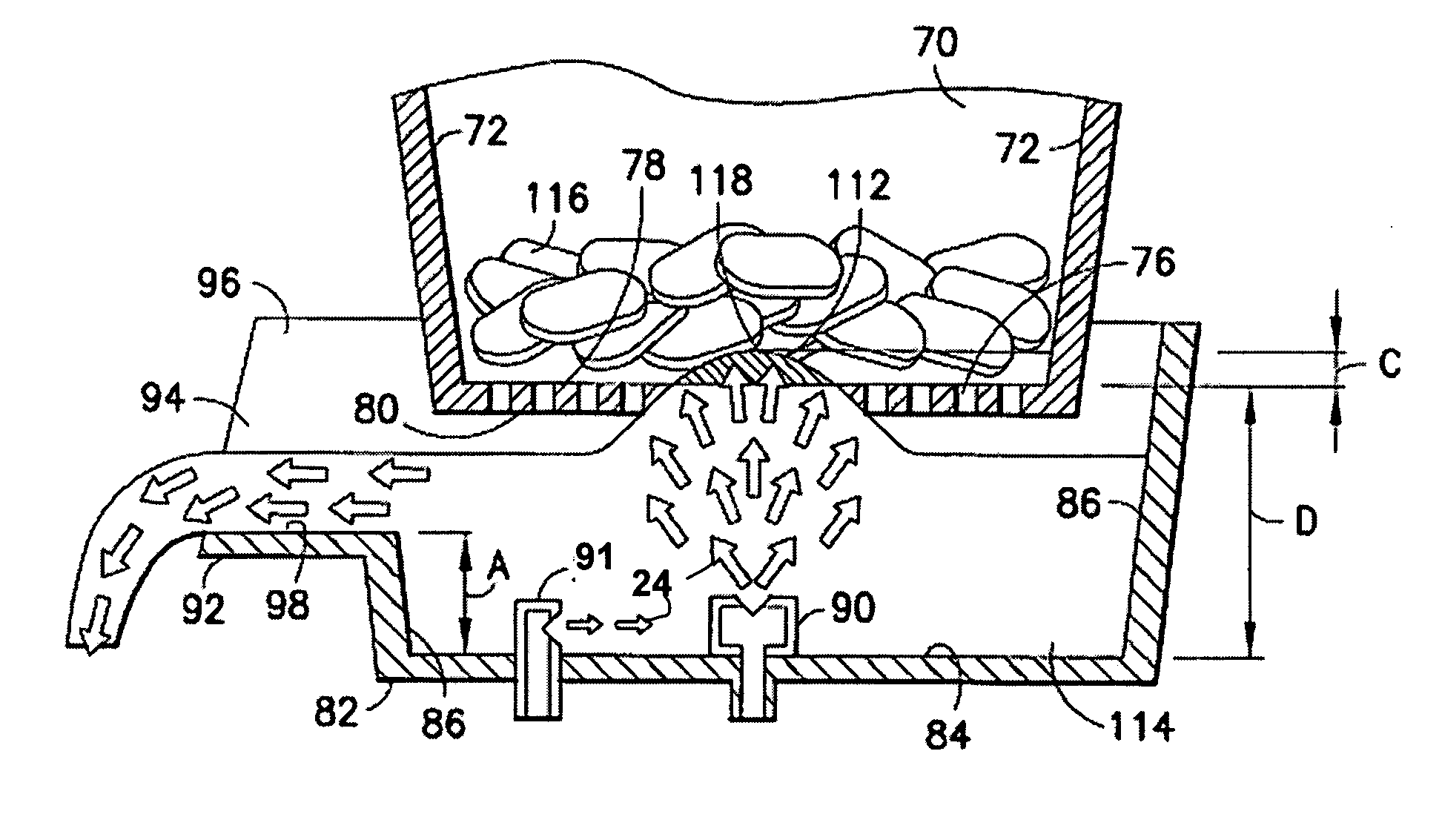
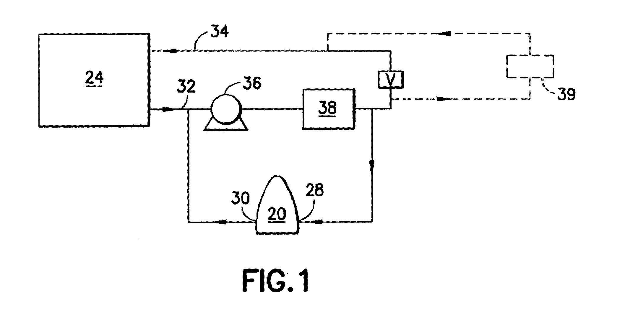
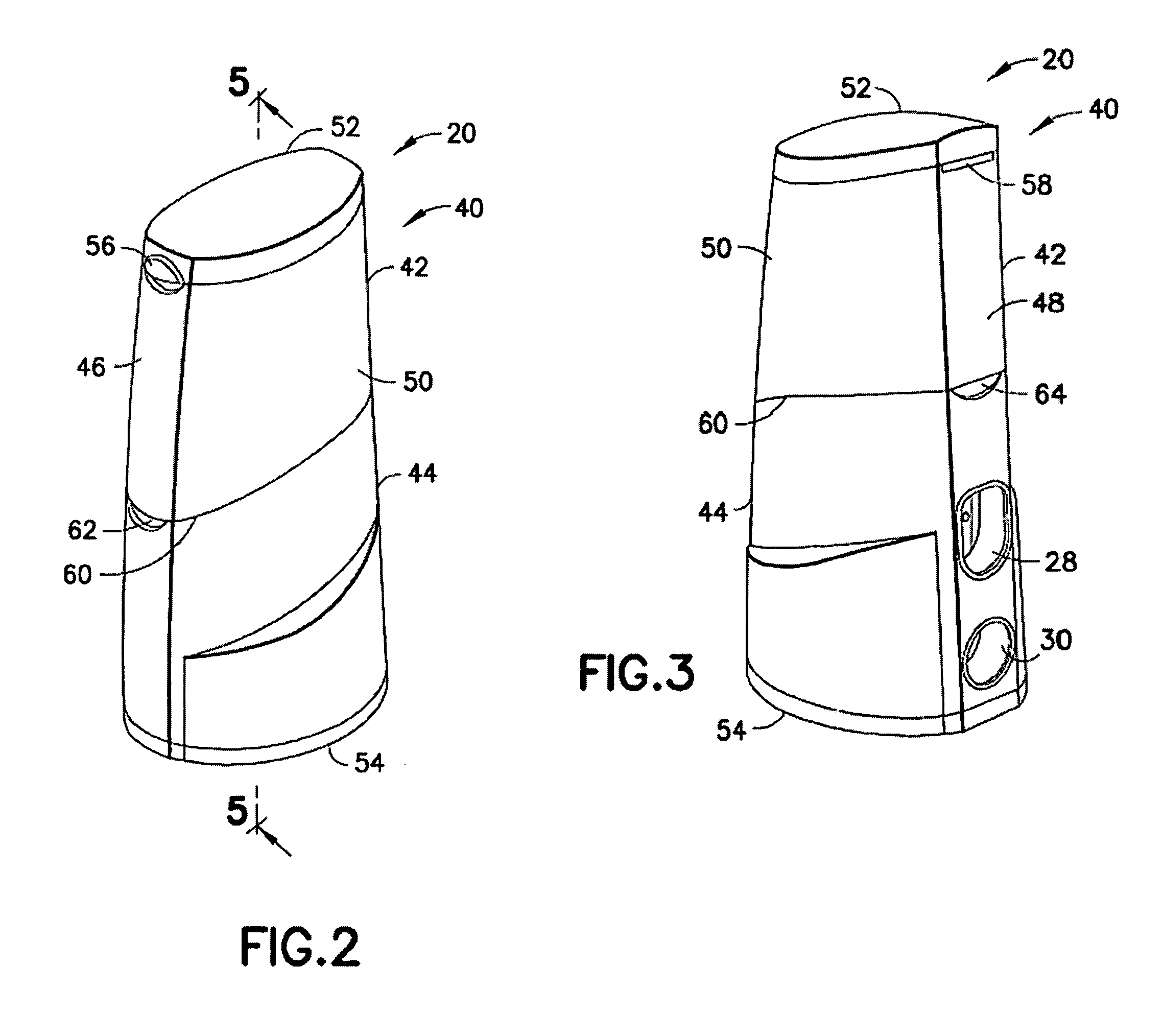
[0023] Referring now to the drawings in which like reference numerals indicate like parts, and in particular to FIG. 1, the present invention is a feeder device 20 for use in a recirculation system 22, which circulates water 24 from a pool 26 through the feeder device. Feeder device 20 typically introduces a chemical solution including chlorine and or other chemicals to water 24 flowing through recirculation system 22. Within recirculation system 22, water 24 enters an inlet 28 of feeder device 20 and exits an outlet 30. Recirculation system 22 generally includes a pool outlet conduit 32 drawing water from pool 26 and a pool return conduit 34 returning water to the pool. Flow through these conduits is induced by a pump 36 with a low pressure (suction) side toward pool outlet conduit 32 and a high pressure side toward pool return conduit 34. Downstream of pump 36, there may be a system filter 38 filtering debris and the like from water flowing from the pump. Because flow out of outle...


PUM

PropertyMeasurementUnit
Diameteraaaaaaaaaa
Diameteraaaaaaaaaa
Diameteraaaaaaaaaa

Abstract

A feeder device for introducing treatment chemicals into a recirculating water stream from a swimming pool. The feeder device includes a housing having a top and bottom portions. A funnel-like hopper having sidewalls and an open bottom forms the inside of the top portion. A grid at least partially closes the open bottom of the hopper. The grid includes a top surface and a bottom surface. One or more chemicals such as chlorine are contained within the sidewalls of the hopper and supported by the top surface of the grid. A dissolving cup having a bottom surface and sidewalls is positioned within the bottom portion. The sidewalls include an opening or notch of a predetermined cross-sectional area formed therein. The bottom surface includes a center nozzle oriented vertically toward the bottom surface of the grid and an off-center nozzle adapted to direct the fluid horizontally in the dissolving cup.

Description

CROSS-REFERENCE TO RELATED APPLICATIONS [0001] This patent application is a continuation-in-part of U.S. Provisional Patent Application Ser. No. 60 / 338,386 entitled “Chemical Feeder” that was filed on Dec. 4, 2001; U.S. Provisional Patent Application Ser. No. 60 / 392,727 entitled “Chemical Feeder” that was filed on Jun. 27, 2002; and U.S. Nonprovisional patent application Ser. No. 10 / 307,671 entitled “Chemical Feeder” that was filed on Dec. 2, 2002. The disclosures of the U.S. Provisional Applications and the U.S. Nonprovisional Application are herein incorporated by reference in their entirety.BACKGROUND OF THE INVENTION [0002] (1) Field of the Invention [0003] The present invention generally relates to water treatment. In particular, the present invention is directed to feeders for introducing treatment chemicals into a recirculating water stream from a swimming pool or the like. [0004] (2) Description of the Related Art [0005] If untreated, swimming pool water provides a hospitabl...

Claims


Application Information

Patent Timeline
IPC IPC(8): B01D37/02C02F1/50B01F1/00B01F15/02C02F1/68C02F1/76E04H4/12
CPCB01D37/025B01F1/0033C02F1/688E04H4/1281C02F2103/42C02F2209/40C02F1/76Y10T137/4891B01F21/221
Inventor BLANCHETTE, DAVID W.ZETENA, CHRISTOPHER M.PALOIAN, MICHAELORCHARD, ANTHONY R.
Owner INNOVATIVE WATER CARE LLC
Why Eureka
Try Eureka