
Antenna device and array antenna

a technology of array antenna and antenna device, which is applied in the direction of slot antenna, polarised antenna unit combination, antenna, etc., can solve the problems of cross-polarization at the antenna radiation pattern, fading risk decreases, and design is asymmetrical

Inactive Publication Date: 2008-07-22
HIGHBRIDGE PRINCIPAL STRATEGIES LLC AS COLLATERAL AGENT
View PDF8 Cites 161 Cited by
  • Summary
  • Abstract
  • Description
  • Claims
  • Application Information

AI Technical Summary

Benefits of technology

"The present invention provides an antenna device and manufacturing method that solves the problem of needing a substrate to support the antenna. The device includes a feeding line in the metal sheet layer that intersects a slotline, allowing for a symmetrical antenna structure that reduces cross-polarization. The device is low-cost, easy to manufacture, and can be used for both reception and transmission. It is also lightweight and can act as a cooling flange for active modules. Additionally, the device does not have static charge build-up as only a single metal layer is used for the antenna element."

Problems solved by technology

If two polarizations are used, the risk of fading decreases as both polarizations would have to fade at the same time.
This design is, however, asymmetrical when looking towards the edge of the laminate where the tapered slot emerges, as there is a feeding line on one side of the laminate and a tapered slot structure on the other side.
This asymmetry may result in cross-polarization at the antenna radiation pattern.
A problem with this symmetrical Vivaldi antenna element design is that so-called parallel plate modes appear in the substrate material, i.e. undesired propagation of electromagnetic radiation.
This dual sided tapered slot antenna with vias for mode suppression ends up in a rather complicated substrate configuration, especially in an array configuration.
The use of substrates renders dielectric losses and also makes the final antenna quite heavy.
The use of substrate materials is also disadvantageous when an antenna is meant to be used for space applications, i.e. in a satellite, as electrostatic build-ups in the plastic material may result in discharges that could be fatal for adjacent electronic circuits.
The common PTFE substrates are also relatively expensive.

Method used


Image

  • Antenna device and array antenna
  • Antenna device and array antenna
  • Antenna device and array antenna

Examples


Embodiment Construction

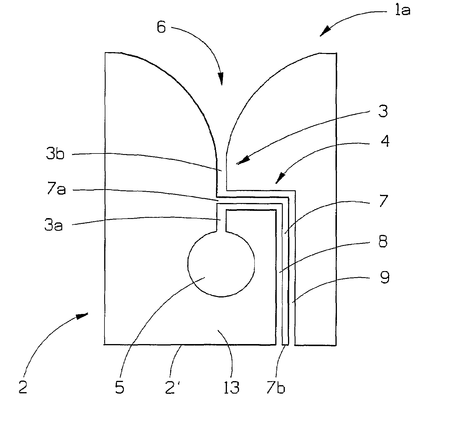
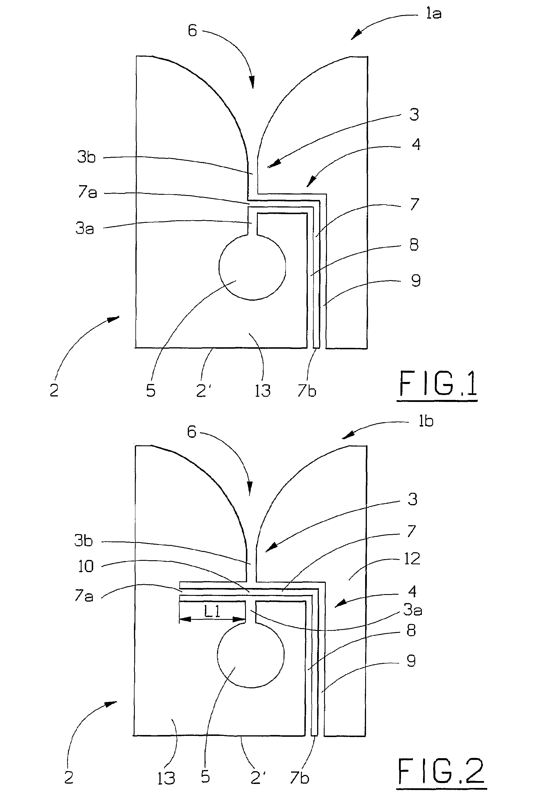
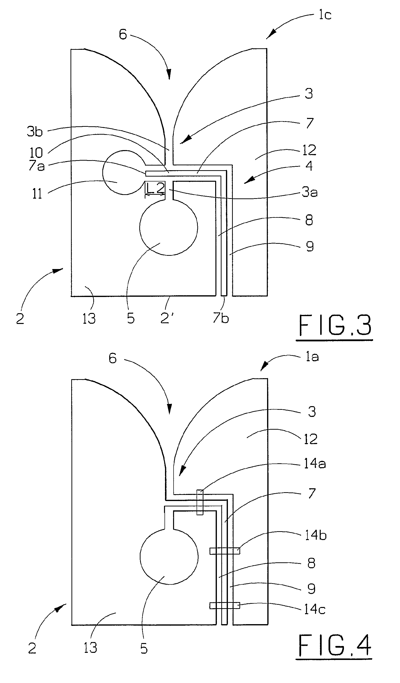
[0049]In FIG. 1, a schematic view of an antenna device in the form of a tapered slot antenna element 1a, for example of the “Vivaldi” type, is shown. The tapered slot antenna 1a comprises a metal layer 2 with a slotline 3 having a first part 3a and a second part 3b, which slotline 3 is fed by a feed line 4. An essentially two-dimensional slot cavity 5 terminates the first part 3a of the slotline 3. The second part 3b of the slotline 3 transcends into an open-ended tapered slot 6, thus forming a radiating element. The tapered slot antenna element 1a is made from only one single metal layer 2, forming a ground plane, where the feed line 4 is incorporated in this metal layer. The feed line is of the type co-planar waveguide (CPW), which comprises a feeding part 7 in the form of a centre conductor 7 separated from the surrounding ground plane 2 by gaps 8, 9. The feed line 4 and its centre conductor 7 intersects the slotline 3, dividing it into the first part 3a and the second part 3b. T...


PUM


Abstract

The present invention relates to a broadband non-resonant antenna device for wireless transmission of information using electromagnetic signals, comprising a metal sheet layer, forming a plane, with a slotline that comprises a first part and a second part. The side of the second part that is the most distant from the first part transcends into a widening open-ended tapered slot in the metal sheet layer. The device additionally comprises a feeding line in the metal sheet layer. The feeding line comprises a feeding part, with a first end and a second end, and gaps separating the feeding part from the surrounding metal sheet layer by a certain distance, where the slotline is intersected by the feeding line.

Description

[0001]This application is the US national phase of international application PCT / SE2004 / 002011 filed 27 Dec. 2004, which designated the U.S. and claims priority to PCT / SE2003 / 002102 filed 30 Dec. 2003, the entire content of each of which is hereby incorporated by reference.TECHNICAL FIELD[0002]The present invention relates to a broadband non-resonant antenna device for wireless transmission of information using electromagnetic signals, comprising a metal sheet layer, forming a plane, with a slotline that comprises a first part and a second part, where the side of the second part that is the most distant from the first part transcends into a widening open-ended tapered slot in the metal sheet layer.[0003]The present invention also relates to an antenna array comprising a plurality of said antenna devices.BACKGROUND ART[0004]In systems for wireless transmission of information using electromagnetic signals, for example radar and cellular telephony or some other telecommunication area, ...

Claims


Application Information

Patent Timeline
Patent Type & Authority Patents(United States)
IPC IPC(8): H01Q13/10H01Q13/08H01Q21/00H01Q25/00
CPCH01Q13/085H01Q21/24H01Q21/067H01Q21/064
Inventor SVENSSONHOOK, ANDERSJOHANSSON, JOAKIM
Owner HIGHBRIDGE PRINCIPAL STRATEGIES LLC AS COLLATERAL AGENT
Learn More