Radio communication system and apparatus

a radio communication and apparatus technology, applied in the field of radio communication apparatus, system and method, can solve the problems of large error in channel response calculation result obtained from channel response calculation preamble signal, poor reception error rate, etc., to reduce transmission errors and accurate calculation of channel respons

Inactive Publication Date: 2008-07-22
KK TOSHIBA
View PDF35 Cites 2 Cited by
  • Summary
  • Abstract
  • Description
  • Claims
  • Application Information

AI Technical Summary

Benefits of technology

[0011]It is, therefore, an object of the present invention to provide a radio communication apparatus, system and method, which can accurately calculate a channel response and can reduce any transmission error even when the channel variation is large.
[0013]With this method, when the channel variation is large, the frequency of output of the channel response calculation preamble signal can be increased, and distortion correction that traces the channel variation along with an elapse of time can be made. On the other hand, when the channel variation is small, the frequency of output of the channel response calculation preamble signal can be decreased, and the data transmission efficiency can be improved.

Problems solved by technology

When a channel variation is large with respect to a packet length, the channel response calculation result obtained from the channel response calculation preamble signal has a large error from the channel distortion which is actually superposed on the data.
As described above, in the conventional radio communication system and radio transmission apparatus, a large error is generated between the channel response calculated from the channel response calculation preamble signal and the channel distortion superposed on data due to a channel variation and, as a result, a reception error rate impairs.

Method used


Image

  • Radio communication system and apparatus
  • Radio communication system and apparatus
  • Radio communication system and apparatus

Examples


Embodiment Construction

[0022]A radio transmission system and apparatus according to an embodiment of the present invention will be described hereinafter with reference to the accompanying drawings.

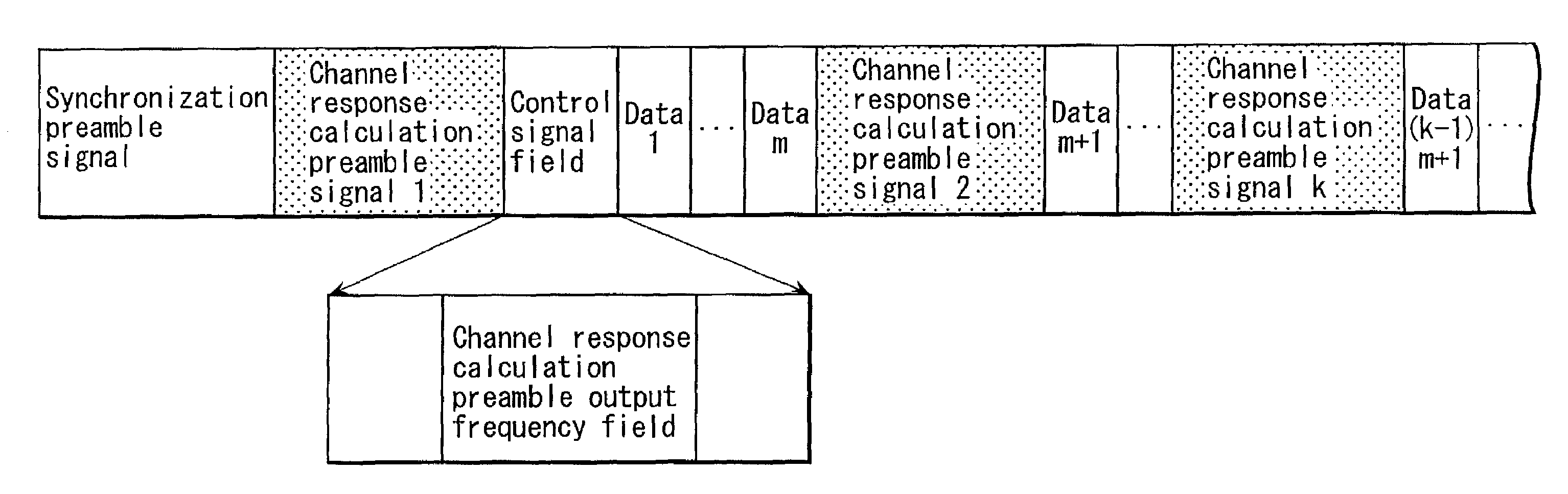
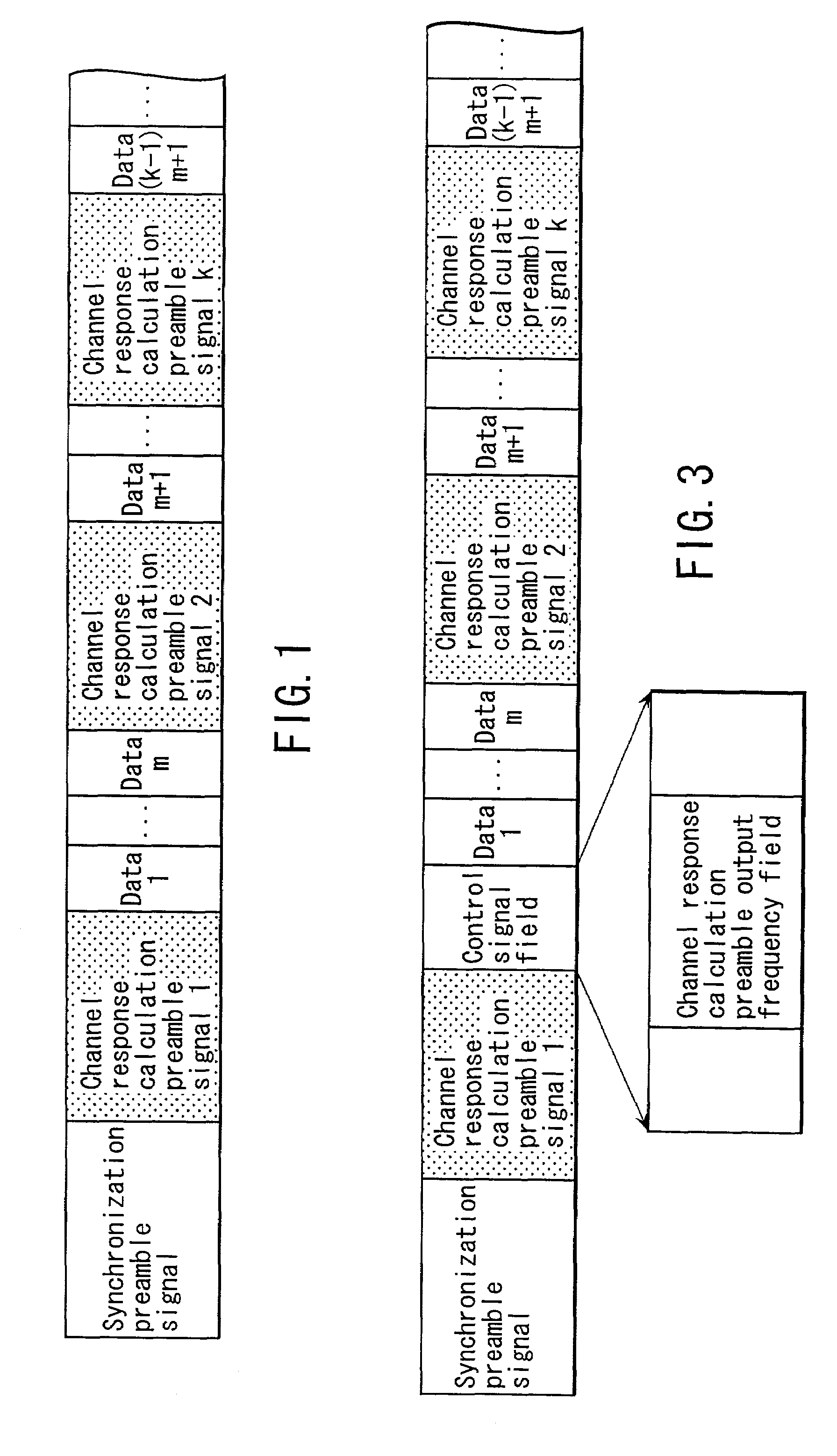
[0023]FIG. 1 shows an example of the transmitted signal format of a radio communication system according to the present invention. A transmitted signal is made up of a synchronization preamble signal, at least one channel response calculation preamble signal (k signals in FIG. 1), and a plurality of data. The number of channel response calculation preamble signals is variable in accordance with a channel variation. The transmitting side controls the frequency of the channel response calculation preamble signal in accordance with the channel variation.

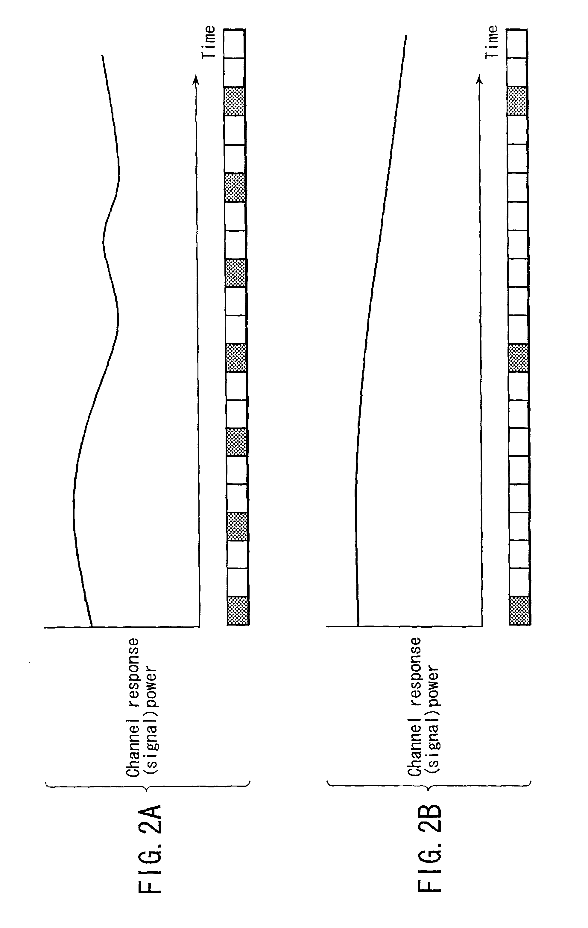
[0024]FIGS. 2A and 2B are examples of graphs showing temporal variations of power as a channel response. The abscissa shows time, and the ordinate shows the intra-band average power of the channel response. FIG. 2A shows a temporal variation of power when the tempor...


PUM


Abstract

A radio communication system for transmitting a radio signal with a transmission format in which a channel response calculation preamble signal serving as a reference upon reception is inserted is disclosed. The output frequency of channel response calculation preamble signals is varied in accordance with a temporal change in radio propagation environment. A channel response variation measurement unit measures a variation of the radio propagation environment. A channel response calculation preamble signal output frequency setting unit sets the output frequency of preamble signals in accordance with the temporal change in radio propagation environment. The preamble signals are inserted in the transmission format to be transmitted at that frequency.

Description

CROSS-REFERENCE TO RELATED APPLICATIONS[0001]This application is based upon and claims the benefit of priority from the prior Japanese Patent Application No. 2001-087040, filed Mar. 26, 2001, the entire contents of which are incorporated herein by reference.BACKGROUND OF THE INVENTION[0002]1. Field of the Invention[0003]The present invention relates to a radio communication apparatus, system and method for transmitting a radio signal in accordance with a transmission format in which a channel response calculation preamble signal serving as a reference is inserted.[0004]2. Description of the Related Art[0005]In recent years, a radio data communication system which can make high-speed data communications indoors or outdoors is required. In a radio communication system that implements high-speed data communications, distortions due to multi-pass interference, i.e., reception of a transmitted signal via various routes due to reflection by buildings, and the like, must be compensated for...

Claims


Application Information

Patent Timeline
Patent Type & Authority Patents(United States)
IPC IPC(8): H04J3/06H04L27/01H04B7/005H04B7/26H04L25/02
CPCH04L25/0226
Inventor SATO, KAZUMI
Owner KK TOSHIBA
Why Eureka
Try Eureka