Rotor recentering after decoupling

a technology of rotor and decoupling, which is applied in the direction of machines/engines, bearing unit rigid support, liquid fuel engines, etc., can solve the problems of fan blade damage, fan damage, and possibly with reduced efficiency, and achieve the effect of avoiding impacts

Active Publication Date: 2008-07-29
SN DETUDE & DE CONSTR DE MOTEURS DAVIATION S N E C M A
View PDF14 Cites 20 Cited by
  • Summary
  • Abstract
  • Description
  • Claims
  • Application Information

AI Technical Summary

Benefits of technology

[0025]Said elastomer ring is advantageously disposed in the bore of the stator structure. This makes it possible to eliminate impacts between the bearing support and the stator structure during decoupling.

Problems solved by technology

The blades of the fan may be damaged following ingestion of foreign bodies, particularly during take off at full revolutions per minute (rpm).
Generally, the fan is strong enough to withstand the effects of ingesting foreign bodies without too much damage being caused, and is capable of continuing to operate, albeit perhaps with reduced efficiency.
In certain circumstances, however, the fan may be damaged to such an extent that it loses pieces of one or more blades.
This results in a major imbalance, which makes it necessary to turn off the engine in order to reduce danger to the aircraft.
Nevertheless, such large imbalance caused by the loss of a blade leads to major cyclical loads which must be accommodated, at least while the engine is running down to reach the windmilling speed of the fan.
Nevertheless, in certain circumstances, the vibration resulting from the imbalance and that persists at the windmilling speed may still be considerable.
But that arrangement requires axial displacement by the open ring on the bearing support, and a device to ensure that the open ring is kept stationary during normal operation, so that it cannot move at an untimely moment during normal operation of the engine, which might prevent subsequent decoupling in the event of excessive imbalance.

Method used


Image

  • Rotor recentering after decoupling
  • Rotor recentering after decoupling
  • Rotor recentering after decoupling

Examples


Embodiment Construction

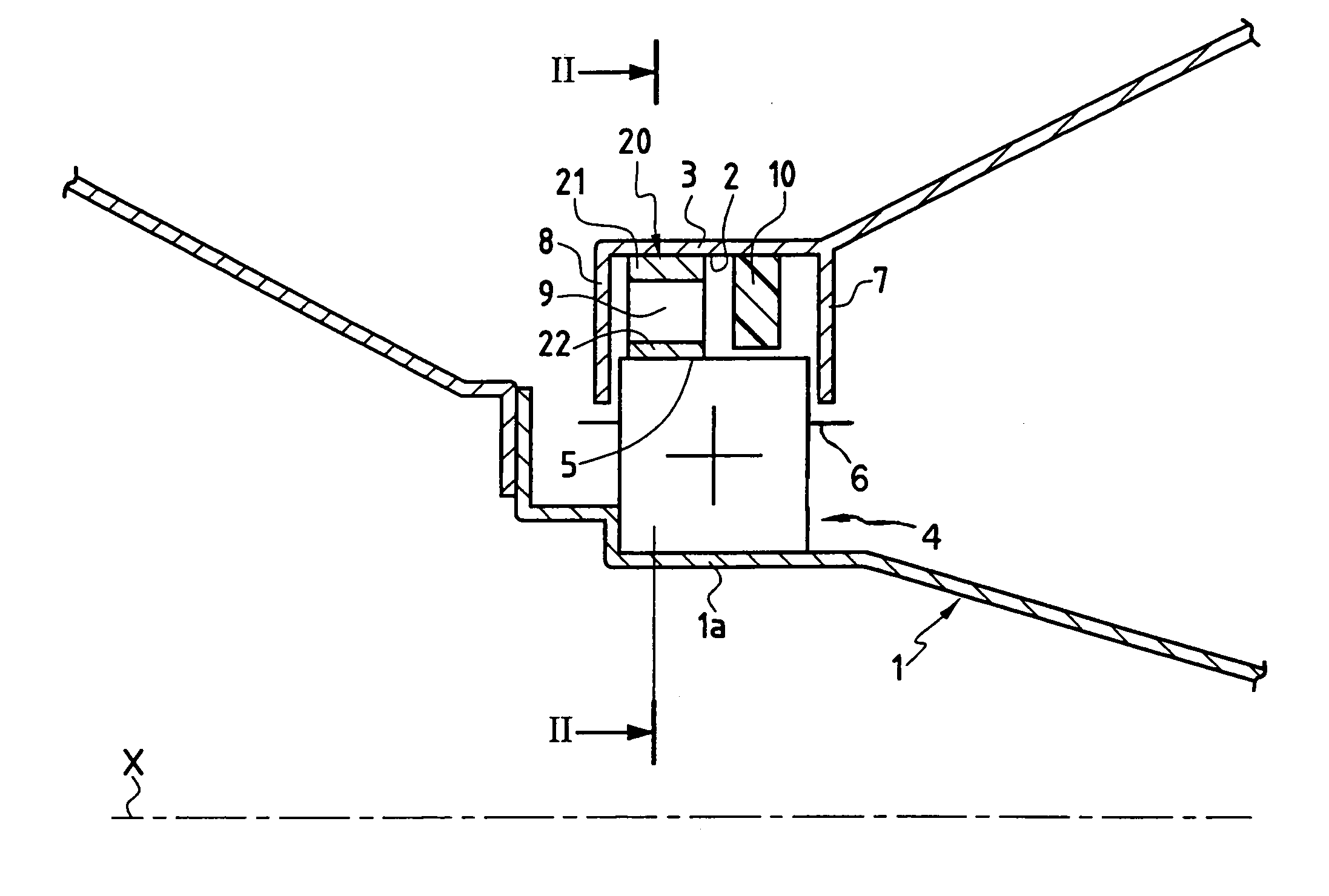
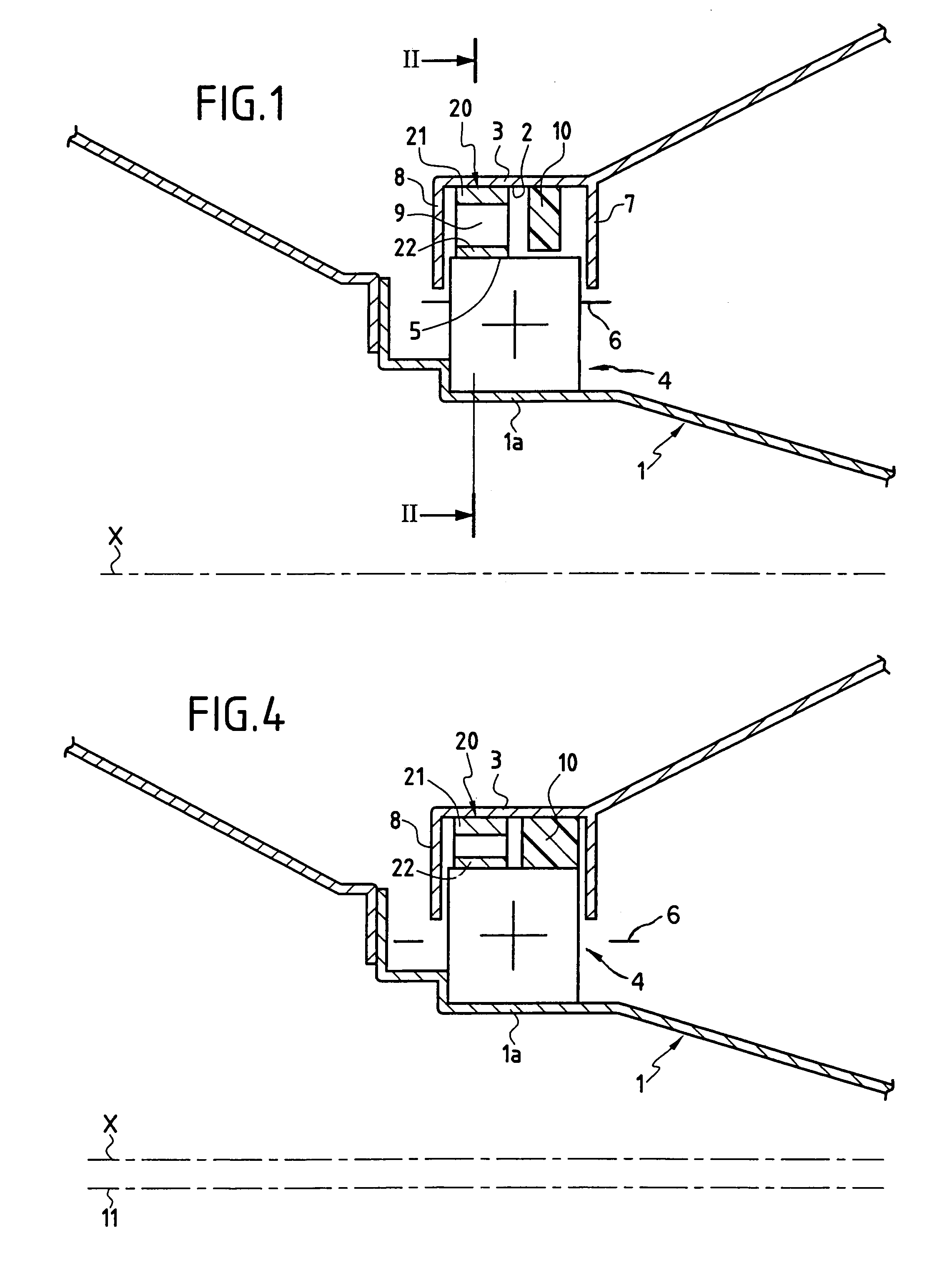
[0033]FIG. 1 is a diagram of the front portion of a shaft 1 for driving a fan in a turbojet of axis X, said shaft being held on the axis X in the bore 2 of a stator structure 3 by means of a bearing 4 having an inside bushing that is assembled snugly on the periphery of a portion 1a of the shaft 1, and having an outside bushing that is held in the bore of a bearing support 5, which bearing support 5 has a diameter that is much smaller than the diameter of the bore 2 of the stator structure 3.

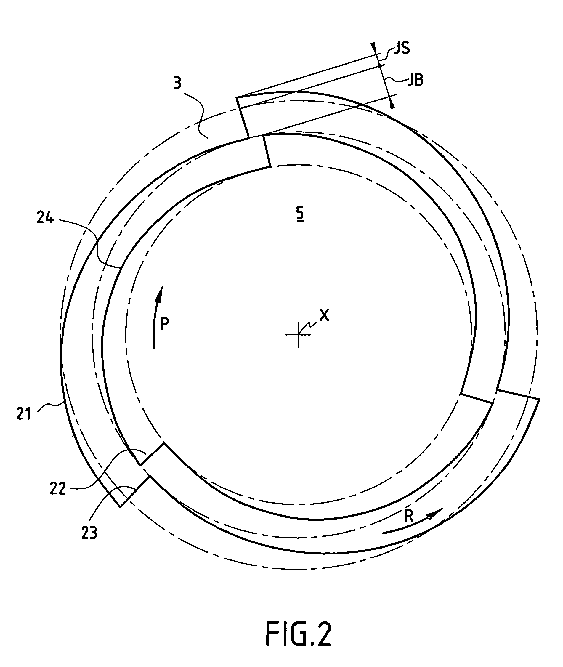
[0034]The bearing support 5 is connected to the stator structure 3 by radially fusible elements, or programmed breaking zones, referenced 6. References 7 and 8 indicate axial abutments that are secured to the stator structure 3 for limiting the axial displacement of the bearing support 5.

[0035]An annular space 9 is thus arranged radially between the periphery of the bearing support 5 and the wall of the stator structure 3 which defines the bore 2. The radial thickness of the space is equal to th...


PUM


Abstract

A recentering device for a rotor shaft for recentering a rotor shaft relative to an axis X of a stator structure in the event of decoupling caused by excessive imbalance. The shaft, in normal operating conditions, lies on the axis X and is radially supported by a bearing support disposed in a bore of the axis X in the stator structure. The bearing support has an outside diameter smaller than the diameter of the bore, to enable the bearing support to orbit about the axis X in the event of decoupling. The bearing support is connected to the stator structure by radially fusible elements. The recentering device recenters the bearing support after decoupling.

Description

BACKGROUND OF THE INVENTIONFIELD OF THE INVENTION[0001]The invention relates to the difficulty of turbomachines remaining intact in the event of decoupling caused by accidental and excessive imbalance.[0002]The invention relates more particularly to the integrity of a turbojet after a fan blade has broken off, for example.DISCUSSION OF THE BACKGROUND[0003]A turbojet comprises an engine which drives a fan that is disposed at the front of the engine.[0004]The blades of the fan may be damaged following ingestion of foreign bodies, particularly during take off at full revolutions per minute (rpm). Generally, the fan is strong enough to withstand the effects of ingesting foreign bodies without too much damage being caused, and is capable of continuing to operate, albeit perhaps with reduced efficiency.[0005]In certain circumstances, however, the fan may be damaged to such an extent that it loses pieces of one or more blades. This results in a major imbalance, which makes it necessary to ...

Claims


Application Information

Patent Timeline
Patent Type & Authority Patents(United States)
IPC IPC(8): F16C23/04F16C41/00F01D25/00F01D1/00F01D21/04F01D25/16F02C7/00F02C7/06F16C19/52F16C23/10F16C35/077
CPCF01D21/045F01D25/16F16C35/077F16C19/52F16C23/10F02C7/06F16C2360/23Y02T50/60
Inventor PLONA, DANIEL
Owner SN DETUDE & DE CONSTR DE MOTEURS DAVIATION S N E C M A
Why Eureka
Try Eureka