Hydraulic tensioner

a technology of hydraulic tensioner and plunger, which is applied in the direction of positive displacement liquid engine, piston pump, gearing, etc., can solve the problems of high production cost, difficulty, and insufficient force exerted by the plunger on the chain, and achieve the effect of suppressing backlash and being easily controlled

Active Publication Date: 2008-07-29
TSUBAKIMOTO CHAIN CO
View PDF20 Cites 18 Cited by
  • Summary
  • Abstract
  • Description
  • Claims
  • Application Information

AI Technical Summary

Benefits of technology

[0009]By virtue of the check valve unit, the hydraulic tensioner can apply proper tension to a timing chain, a timing belt or the like in a vehicle engine. However, the grooves provided on the outer circumferential surface of the ball guide the end surface of the ball seat additionally provide for ventilation of air from the high pressure oil chamber of the tensioner, so that, even if the tensioner is attached in an engine block in such a way that the plunger protrudes downward, air is easily ventilated from the high pressure chamber, and consequently adequate force can be exerted consistently against the chain, backlash noises can be suppressed, and leak down of oil from the high pressure chamber can be easily controlled.
[0010]Where the ball guide is composed of a synthetic resin, ventilating grooves can be easily formed on the outer circumferential surface of the ball guide, thereby making it unnecessary to carry out additional machining of the metal housing or of the ball guide.

Problems solved by technology

The above-described check valve mechanism requires high accuracy machining, and consequently its production cost was high, and difficulties were encountered in the assembly of the tensioner.
Consequently, the force exerted by the plunger on the chain is sometimes insufficient.
In such a case, backlash noises are generated by the chain.

Method used


Image

  • Hydraulic tensioner
  • Hydraulic tensioner
  • Hydraulic tensioner

Examples


Embodiment Construction

[0018]The invention is applicable to various forms of hydraulic tensioners including hydraulic tensioner having a rack formed on plunger for cooperation with a ratchet pawl pivoted on a housing.

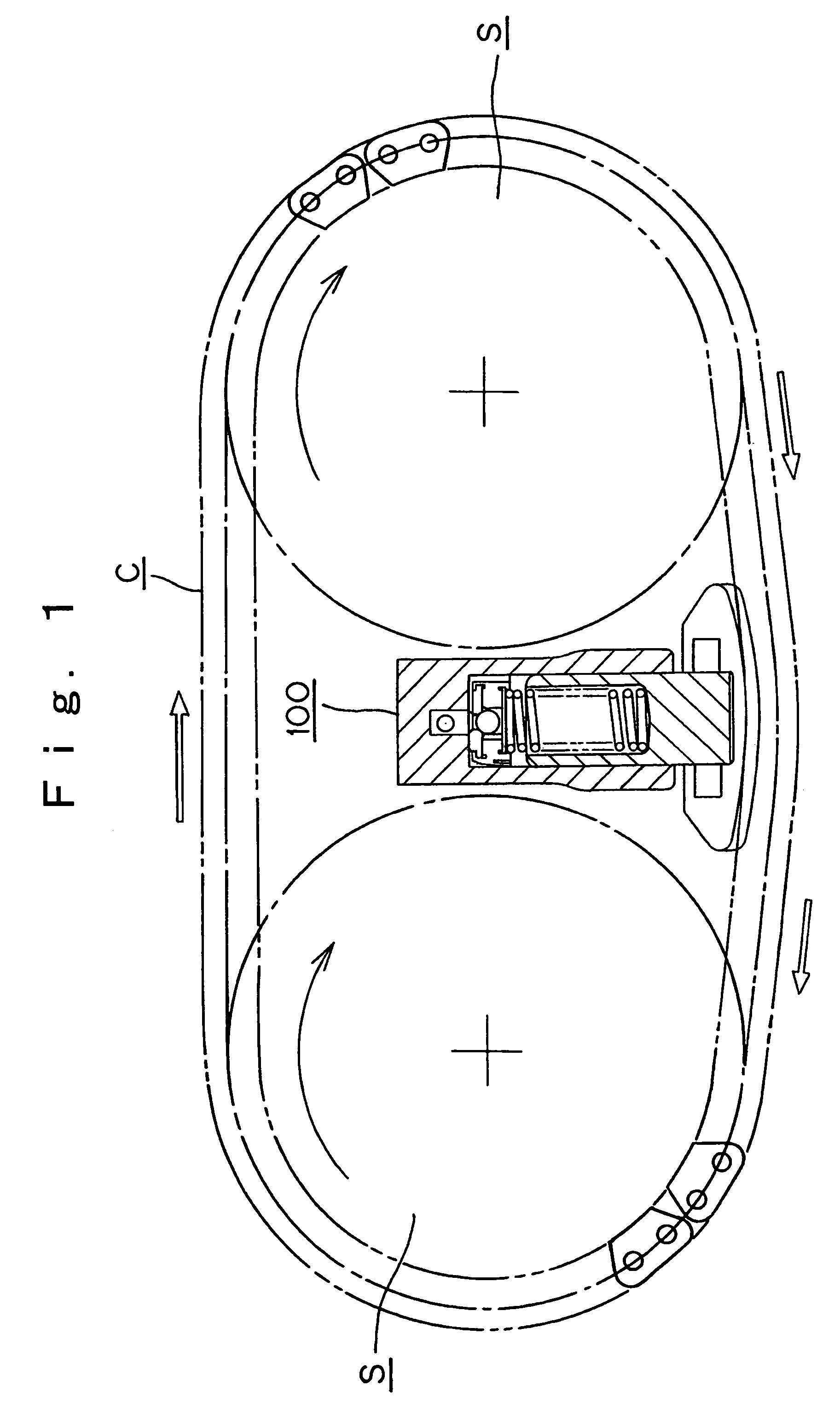
[0019]As shown in FIGS. 1 and 2, a hydraulic tensioner 100, is disposed between a pair of cam sprockets S in such a manner that its plunger protrudes downward from a front surface of its housing in order to maintain tension in a chain C, meshing with the two cam sprockets.

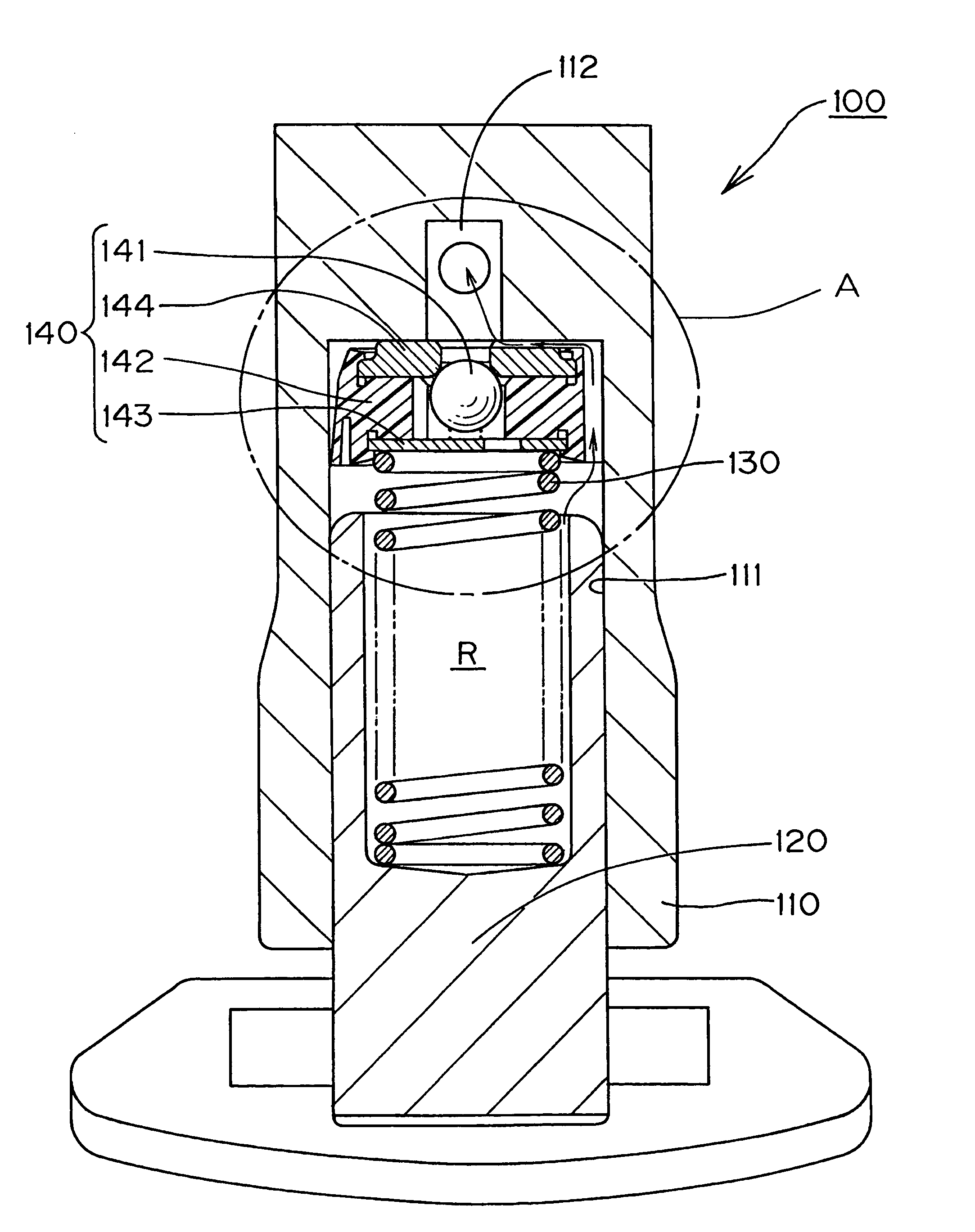
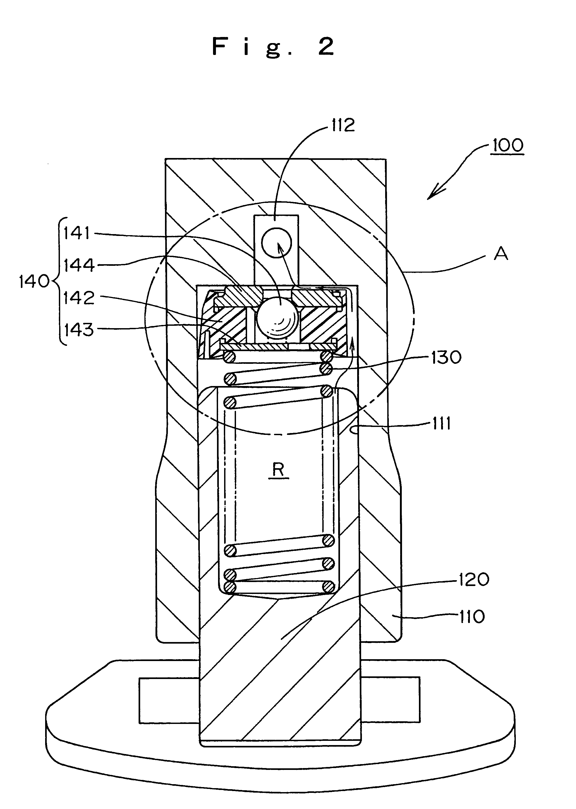
[0020]In the hydraulic tensioner 100, as shown in FIG. 2, the plunger 120, which is outwardly cylindrical, fits slidably in a plunger-accommodating hole 111 formed in a tensioner housing 110. A high pressure oil chamber R is formed between the plunger 120 and the plunger-accommodating hole 111. This chamber accommodates a plunger-biasing coil spring 130, which urges the plunger 120 in a protruding direction.

[0021]A check valve unit 140 is provided adjacent the bottom of the plunger accommodating hole 111, i.e., the end of th...


PUM


Abstract

A check valve unit in a hydraulic tensioner comprises a check ball which controls the flow of the oil to and from a high pressure oil chamber formed by a plunger and the plunger-receiving hole of the tensioner housing, a ball guide in which the check ball moves, a retainer which seals the check ball in the ball guide, and a ball seat which blocks reverse flow of oil by seating the check ball. Grooves, which ventilate air from the high pressure oil chamber to an oil supply passage, are formed on an outer circumferential surface of the ball guide and a bottom surface of the ball seat.

Description

FIELD OF THE INVENTION[0001]This invention relates to a hydraulic tensioner for maintaining proper tension in a traveling, flexible power transmission medium such as a timing chain, a timing belt, or the like, in a vehicle engine.BACKGROUND OF THE INVENTION[0002]Hydraulic tensioners which include a check valve mechanism been widely used to maintain proper tension in timing chains and timing belts which transmit rotation from a crankshaft to one or more camshafts in a vehicle engine. The check valve mechanism is used to prevent vibration generated during the operation of the chain or belt.[0003]A conventional hydraulic tensioner typically includes a check valve mechanism comprises a metal cylinder fitted into a cylindrical plunger-receiving hole formed in a housing, a plunger slidably received in the hole and having an end portion protruding from the housing and biased in the protruding direction by a spring inside the housing, and a high pressure oil chamber formed between the insid...

Claims


Application Information

Patent Timeline
Patent Type & Authority Patents(United States)
IPC IPC(8): F16H7/08F04B17/00F04B35/00
CPCF16H7/0836F16H2007/0859F16H2007/0812F16H2007/0806
Inventor YOSHIDA, OSAMU
Owner TSUBAKIMOTO CHAIN CO
Why Eureka
Try Eureka