Method for calibration and removal of wavefront errors

a wavefront error and calibration method technology, applied in the field of interferometer metrology of surfaces, can solve problems such as degrading the performance of the interferometer, wavefront errors commonly called ray-mapping errors

Active Publication Date: 2008-07-29
ZYGO CORPORATION
View PDF16 Cites 18 Cited by
  • Summary
  • Abstract
  • Description
  • Claims
  • Application Information

AI Technical Summary

Problems solved by technology

These misalignments cause wavefront errors commonly called ray-mapping errors.
Such wavefront errors are often large enough to degrade the performance of the interferometer.

Method used


Image

  • Method for calibration and removal of wavefront errors
  • Method for calibration and removal of wavefront errors
  • Method for calibration and removal of wavefront errors

Examples


Embodiment Construction

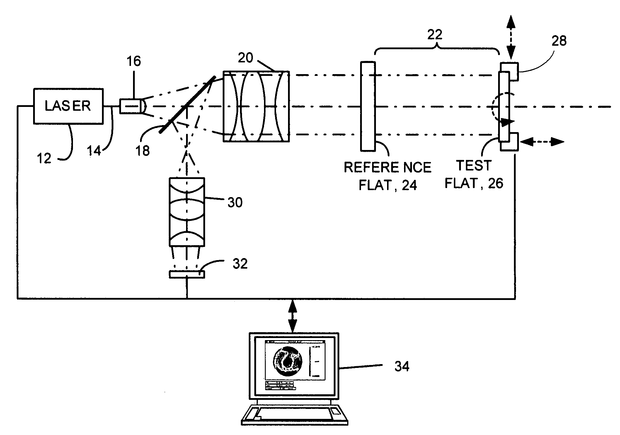
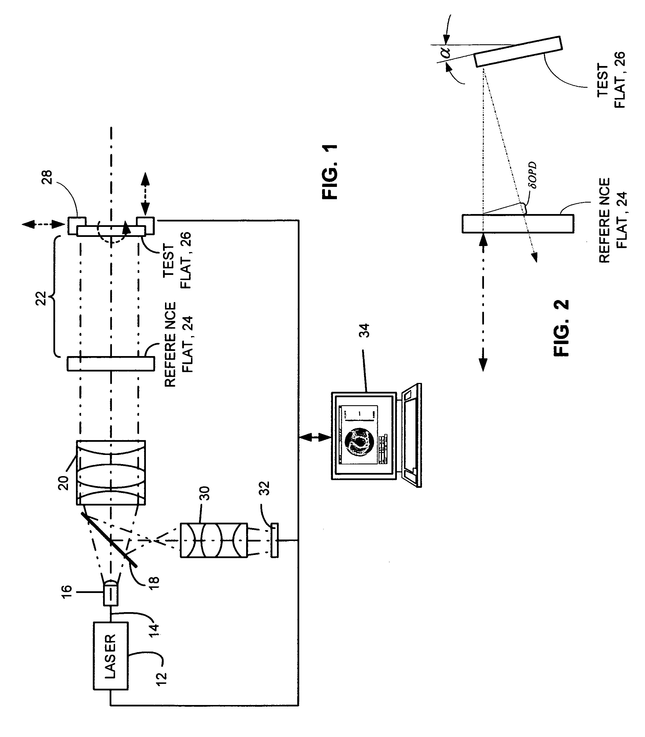
[0025]Reference is now made to FIG. 1, which shows an interferometer in accordance with the invention. The interferometer is generally designated at 10. While shown configured as a Fizeau capable of performing carrier fringe analysis to reduce sensitivity to environmental effects and vibration, the interferometer 10 need not necessarily be a Fizeau to practice the invention. Other types of interferometers, such as Tyman-Green, could also be beneficially employed. The major components of the interferometer 10 are a laser 12 that generates a beam 14 as a source of illumination followed downstream by beam expander and spatial filter combination 16 for diverging the wavefront from laser 12. Placed along this diverging beam is a beam splitter 18 that passes the diverging beam to a collimator 20 that shapes it into a plane wave front that eventually strikes a reference flat 24 and is partially reflected as a reference wavefront and partially transmitted downstream to impinge on a test fla...


PUM


Abstract

Apparatus and methods for generating an empirically determined mathematical model of wavefront error in an interferometer as a function of aperture misalignment and then applying the model to correct subsequent measurements. The methods are useful in Fizeau and other types of interferometers in which carrier fringe analysis may be used for reducing errors caused by environmental and vibration effects.

Description

CROSS REFERENCE TO RELATED APPLICATION[0001]This application claims the benefit of priority from U.S. Provisional Patent Application No. 60 / 625,183 entitled METHOD FOR CALIBRATION AND REMOVAL OF WAVEFRONT ERRORS filed on Nov. 5, 2004, the entire contents of which are incorporated herein by reference.FIELD OF THE INVENTION[0002]This invention in general relates to interferometric metrology of surfaces and more particularly to interferometric apparatus and methods for comparing optical surfaces.BACKGROUND OF THE INVENTION[0003]The problem addressed by the invention is to compare two optical surfaces, spheres or aspheres, which have nominally the same shape. This may done with a Fizeau-interferometer system by placing the first surface—called the master calibration surface—in front of the Fizeau reference surface and making a measurement of the resulting phase-difference of the light reflected off the Fizeau-reference surface and the master calibration surface. This result is stored. N...

Claims


Application Information

Patent Timeline
Patent Type & Authority Patents(United States)
IPC IPC(8): G01B11/02
CPCG01J9/02G01M11/005G01B9/02061G01B9/02057G01B9/02072
Inventor SMYTHE, ROBERT A.BATTISTONI, DONALD S.
Owner ZYGO CORPORATION
Why Eureka
Try Eureka