Workpiece regrasping system for robot

a robot and workpiece technology, applied in the direction of electric programme control, program control, instruments, etc., can solve the problems of actual workpiece orientation, inconvenient operation, and difficulty in the practice of changing the workpiece orientation of the robo

Inactive Publication Date: 2008-07-29
FANUC LTD
View PDF5 Cites 5 Cited by
  • Summary
  • Abstract
  • Description
  • Claims
  • Application Information

AI Technical Summary

Benefits of technology

[0006]It is an object of the present invention to provide a workpiece regrasping system for a robot, which allows the robot to perform the handling of a workpiece while changing an actual workpiece orientation to a desired workpiece orientation, without applying an excessively large load to the wrist of the robot, even when the objective workpiece is heavy in weight.

Problems solved by technology

For example, in an operation for picking up a workpiece by a hand and placing it on a pallet, such an inconvenience may occur that an actual workpiece orientation just before a picking-up step is different from a desired workpiece orientation on a pallet on which the workpiece is placed (e.g., the difference of a 90° orientation, between the vertical and horizontal orientations of a rectangular parallelepiped body).
However, if the workpiece is heavy, such as a large-sized motor or an engine component, the handling operation for changing the workpiece orientation generally applies an excessively large load to a wrist of the robot, so that it is difficult, in practice, for the robot to change the workpiece orientation.

Method used


Image

  • Workpiece regrasping system for robot
  • Workpiece regrasping system for robot
  • Workpiece regrasping system for robot

Examples


first embodiment

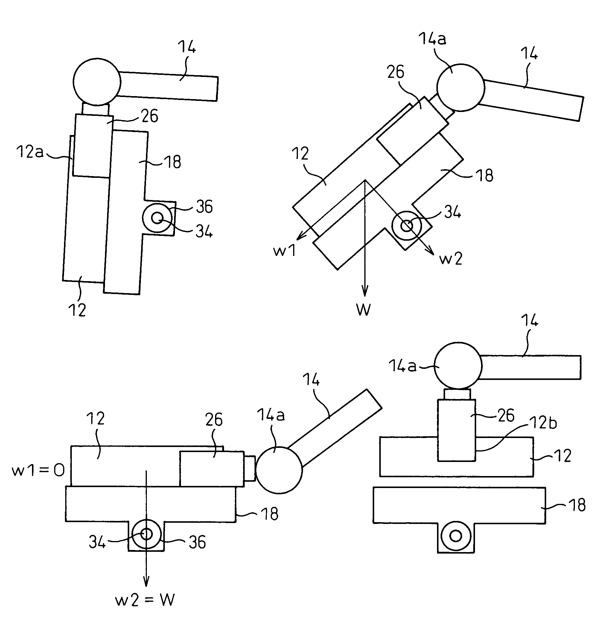
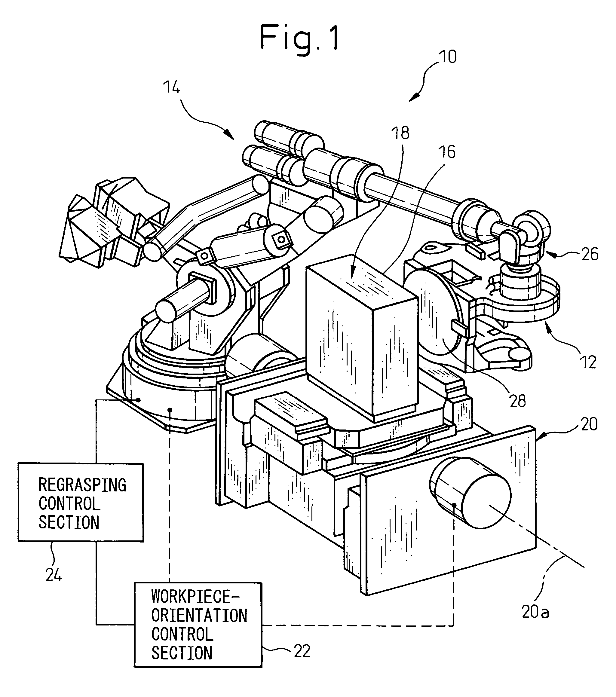
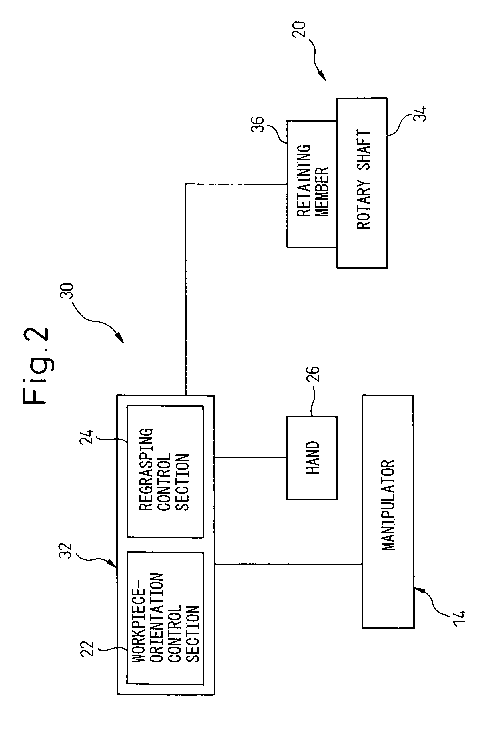
[0029]FIG. 2 illustrates a workpiece regrasping system 30 according to the present invention. FIG. 3 illustrates a positional relationship between a workpiece 12, a manipulator 14 and a deck member 18, just before a workpiece regrasping process starts. FIGS. 4A to 4D illustrate the positional relationship between the workpiece 12, the manipulator 14 and the deck member 18 in a series of steps of the workpiece regrasping process.

[0030]In the workpiece regrasping system 30, the above-described workpiece-orientation control section 22 and the regrasping control section 24 are incorporated into a robot control unit 32 connected to the manipulator 14 (i.e., they may be constituted by a single CPU). The support mechanism 20 rotatably supports a rotary shaft 34 (having the axis 20a) integrally coupled with the deck member 19, and includes a retaining member 36 for releasably retaining the rotary shaft 34 at a certain rotational position. The robot control unit 32 (or the workpiece-orientat...

second embodiment

[0040]In the above embodiment, the rotary shaft 34 provided in the deck member 18 rotates in accordance with the hand-orientation changing operation of the manipulator 14 (in other words, the driving force of the rotary shaft 34 is given from the manipulator 14 via the deck member 18), but alternatively, the rotary shaft 34 of the deck member 18 may rotate in a positive manner under a driving force of an exclusive drive source. In this alternative case, while a drive mechanism having a servomotor for driving the rotary shaft 34 may be provided separately from a robot control system, it is also possible to drive the rotary shaft 34 by an additional control axis (or a control axis other than the control axes of the manipulator 14) in the robot control system. The configuration of a workpiece regrasping system 40 having the latter structure, which is the present invention, will be described below with reference to FIG. 6.

[0041]In the workpiece regrasping system 40, the above-described ...


PUM

PropertyMeasurementUnit
rotation angleaaaaaaaaaa
angleaaaaaaaaaa
weightaaaaaaaaaa

Abstract

A workpiece regrasping system for a robot. The system includes a manipulator grippable a workpiece; a deck member having a deck surface on which a workpiece is placeable; a support mechanism rotatably supporting the deck member about an axis parallel to the deck surface; a workpiece-orientation control section for controlling the manipulator so as to grip a workpiece at a first point of the workpiece and to bring the workpiece into abutment with the deck surface of the deck member, and configured to displace the workpiece together with the deck member about the axis, while maintaining a mutually abutted condition, until the workpiece occupies a desired orientation, with at least a part of a weight of the workpiece being carried on the deck surface; and a regrasping control section for controlling the manipulator so as to temporarily release the workpiece placed on the deck surface in the desired orientation and to regrasp the workpiece at a second point different from the first point. The workpiece-orientation control section may control an operation of the manipulator, or control a rotational drive section for the deck member, while maintaining the workpiece in abutment with the deck surface, to displace the workpiece to the desired orientation.

Description

BACKGROUND OF THE INVENTION[0001]1. Field of the Invention[0002]The present invention relates to a workpiece regrasping system for a robot.[0003]2. Description of the Related Art[0004]In a configuration wherein a robot performs handling of a workpiece, there is a case, as in the orientation of a workpiece which should be gripped or held by a hand (or a workpiece orientation), where the workpiece orientation desired by the robot does not coincide with an actual workpiece orientation provided at an actual working site (such as, the orientation of the workpiece placed on a predetermined jig, or the orientation of the workpiece fed from a machine tool). For example, in an operation for picking up a workpiece by a hand and placing it on a pallet, such an inconvenience may occur that an actual workpiece orientation just before a picking-up step is different from a desired workpiece orientation on a pallet on which the workpiece is placed (e.g., the difference of a 90° orientation, between...

Claims


Application Information

Patent Timeline
Patent Type & Authority Patents(United States)
IPC IPC(8): H01L21/68G05B19/18B21C49/00G06F19/00B25J9/10B25J9/00B25J9/16B25J15/00
CPCB25J9/1612B25J9/0096
Inventor HARIKI, KAZUOOTSUKA, KAZUHISAODA, MASARU
Owner FANUC LTD
Why Eureka
Try Eureka