
Apparatus comprising armor

a technology of armor and armor plate, applied in the field of armor plate, can solve the problems of limited armor that can be used, missile explosion, and destruction of ships, and achieve the effect of reducing the likelihood of sympathetic detonation and limiting the effect of strategic hits

Inactive Publication Date: 2008-08-05
LOCKHEED MARTIN CORP
View PDF19 Cites 37 Cited by
  • Summary
  • Abstract
  • Description
  • Claims
  • Application Information

AI Technical Summary

Benefits of technology

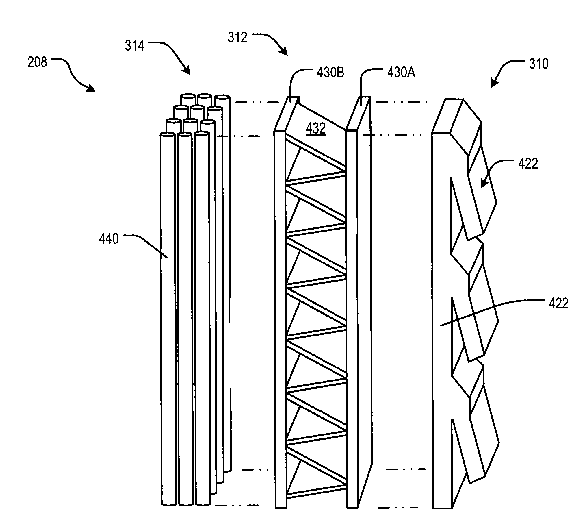
The present invention provides an improved armor for missile cells that reduces the impact of strategic hits and prevents detonation in multi-cell launchers. The armor is multi-layered and includes a first layer that undergoes explosive welding, a second layer that inelastically deforms, and a third layer that prevents sympathetic explosions and stemming of fire. The armor absorbs blast energy, restricts the scatter of blast fragments, and retards the spread of fire. The first layer is made of a metallic plate and fins that weld to the plate, and the second layer is made of a sandwich structure that absorbs blast energy and dampens the pressure wave. The third layer comprises pressurized tubes that function as a shock dampener, fire retardant, and high-velocity particle trap. The armor is lightweight and provides enhanced ability to contain blast fragments without adding weight or cost.

Problems solved by technology

If one of the missiles in launcher 100 is hit by an incoming ordinance, it is likely that the missile will explode.
While a ship, especially a larger one, will be able to withstand a strike from a single missile, sympathetic detonation of multiple missiles within launcher 100 can cause a catastrophic event; namely, destruction of the ship.
Unfortunately, the weight of the armor is also proportional to its thickness, which constrains the amount of armor that can be used.

Method used


Image

  • Apparatus comprising armor
  • Apparatus comprising armor
  • Apparatus comprising armor

Examples


Embodiment Construction

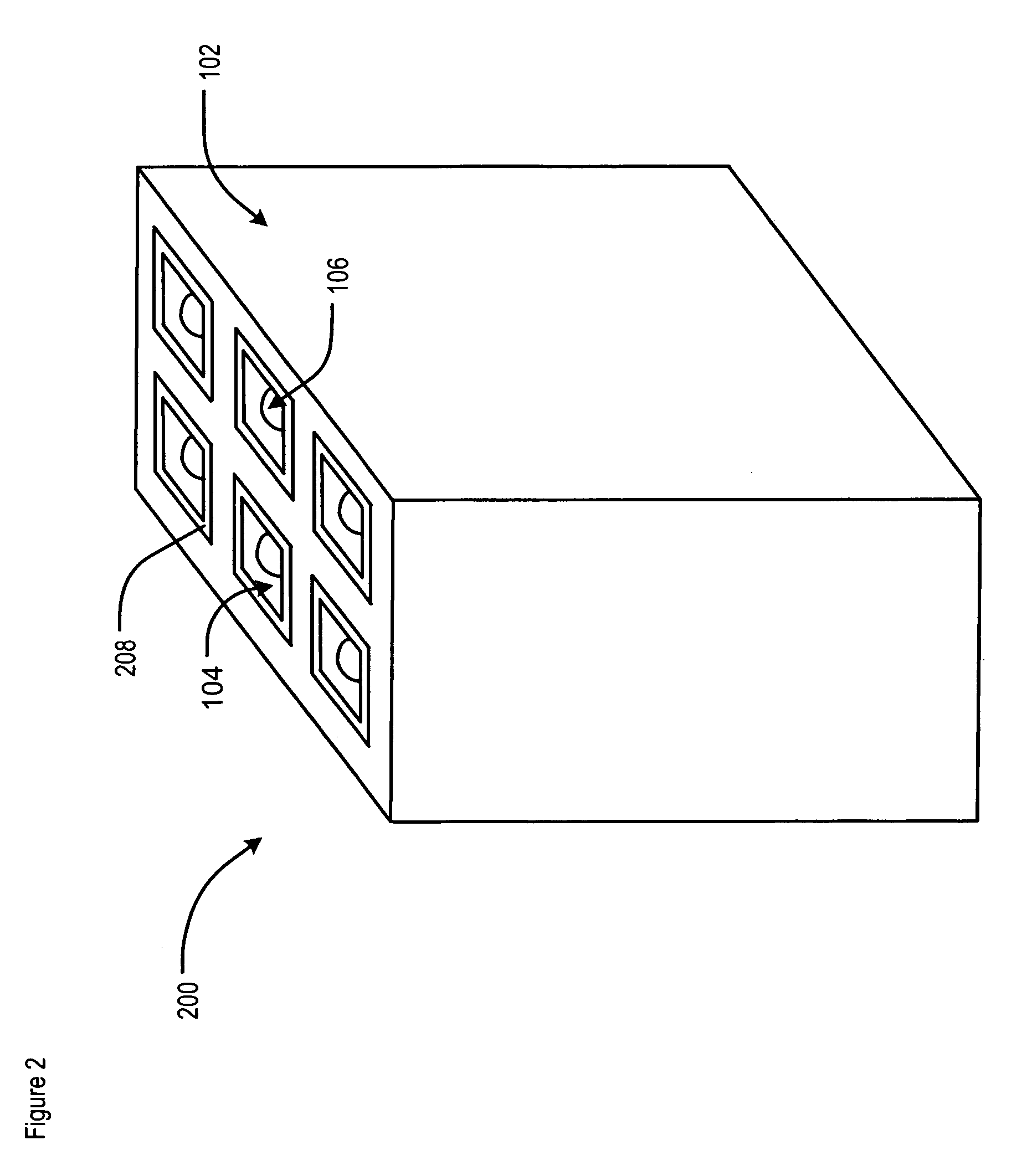
[0029]FIG. 2 depicts multi-cell launcher 200 in accordance with the illustrative embodiment of the present invention. Launcher 200 includes launcher body 102, cells 104, and armor 208, arranged as shown. The launcher depicted in FIG. 2 includes six cells 104, each of which contain missile 106. It is understood, however, that some other embodiments of the launcher contain a greater (or lesser) number of cells.

[0030]In the embodiment that is depicted in FIG. 2, armor 208 lines the interior of cells 104. In some other embodiments, armor 208 is situated at the exterior of each cell 104. That is, armor 208 is incorporated into launcher body 102.

[0031]FIG. 3 depicts a top view of one of the cells 104 of launcher 200. In this embodiment, armor 208 has three layers: first layer 310, second layer 312, and third layer 314. In the illustrative embodiment, first layer 310 is the inner-most layer (i.e., proximal to missile 106), second layer 312 is the middle layer, and third layer 314 is the ou...


PUM

PropertyMeasurementUnit
tensile elongationaaaaaaaaaa
lengthaaaaaaaaaa
lengthaaaaaaaaaa

Abstract

An armor that is used, for example, in multi-cell missile launchers is disclosed. In some embodiments, the armor includes three layers. The inner-most layer undergoes explosive welding when exposed to a pressure wave from an explosion. An intermediate layer in-elastically deforms when exposed to the explosion. The third and outer-most layer includes a plurality of elongated, pressurized tubes that contain fire retardant, among other chemicals. Silicone gel is interposed between the tubes.

Description

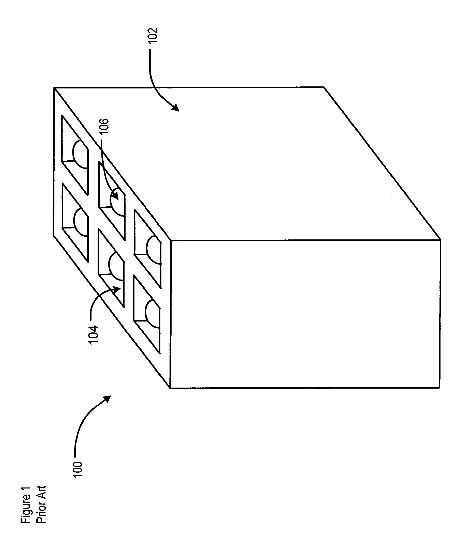
FIELD OF THE INVENTION[0001]The present invention relates generally to armor, such as can be used to improve the survivability of a missile launcher.BACKGROUND OF THE INVENTION[0002]FIG. 1 depicts conventional multi-cell missile launcher 100. The launcher comprises launcher body 102, which contains a plurality of compartments or cells 104. Each cell is capable of launching missile 106. Multi-cell missile launcher 100 is often used on ships and military vehicles.[0003]Since it is an offensive weapon, launcher 100 is likely to be targeted by enemy combatants. Due to its heat signature, launcher 100 is often one of the more detectable features on the deck of a ship. If one of the missiles in launcher 100 is hit by an incoming ordinance, it is likely that the missile will explode. Explosion of one of the missiles within launcher 100, whether due to a strategic hit or simply a malfunction, can trigger sympathetic detonation of other missiles within launcher 100. While a ship, especially ...

Claims


Application Information

Patent Timeline
Patent Type & Authority Patents(United States)
IPC IPC(8): F41H5/04B23K20/08
CPCF41H5/04F41H5/0442F42D5/045F42B39/16F42B39/24F42B39/14
Inventor SHAH, TUSHAR K.MAHESHWARI, MAHENDRAKLEIN, GREG W.
Owner LOCKHEED MARTIN CORP
Learn More