
Self-stabilizing suspension and hoisting system

Inactive Publication Date: 2008-08-05
BELLANTONI JOHN F
View PDF11 Cites 8 Cited by
  • Summary
  • Abstract
  • Description
  • Claims
  • Application Information

AI Technical Summary

Benefits of technology

[0018]This invention is directed to a hoist and load suspension system for raising or lowering a rigid beam that supports a large load including: a first line supporting the rigid beam, with unequal first mechanical advantage and second mechanical advantage on either side of the load; a second line supporting the same rigid beam under the load, with a third mechanical advantage and a fourth mechanical advantage o

Problems solved by technology

In lifting large loads, it is often inconvenient or impossible to provide for cables or structural members that pass overhead across the load.
This is particularly true of large loads, such as vessels or machinery, or in mobile applications in which it is difficult or expensive to transport a large overhead structure to a remote location.
In addition, it is desirable in most applications to lift and lower the load without allowing it to tilt, which can affect liquids in the load, and which can move the center of gravity of the load to one side or the other, rendering the system unstable.
This '171 patent suffers from reliance on friction between cable and pulley to prevent the downward force from lowering one end of the load.
In many applications, maintaining a friction-free contact between pulley and cable is difficult because of the presence water, grease, and dirt on the cables.
Moreover, the two cable circuits are of unequal length, which results in unequal elongation under temperature variations, which will tend to make one or the other cable prone to slipping.
This requires frequent replacement of the cable, or the use of a non-corrosive cable material, which adds considerably to the cost of installation and maintenance.
This patent does not provide a mechanism to prevent the boat from rotating as it is raised or lowered, and is limited to small craft because of the configuration of the lifting beams.
It does not provide for stabilization against accidental roll of the boat.
Further, it requires that part of the cable be immersed in the water while the boat is in the lifted position, which has the same disadvantages as U.S. Pat. No. 5,427,471.
It is seen that all the above load lifting patents provide raising and lowering of a large load without cables or structural members passing over the load, but either allow de-stabilizing rotation of the load, or have one or more substantive disadvantages such as requiring mechanisms substantially more complex than a pulley and cable system, or restricting the location and type of pulleys and cable fastenings, or depending upon frictional resistance to rotation of the load.
Other limitations of the related art will become apparent to those skilled in the art upon a reading of the specification and a study of the drawings.

Method used


Image

  • Self-stabilizing suspension and hoisting system
  • Self-stabilizing suspension and hoisting system
  • Self-stabilizing suspension and hoisting system

Examples


Embodiment Construction

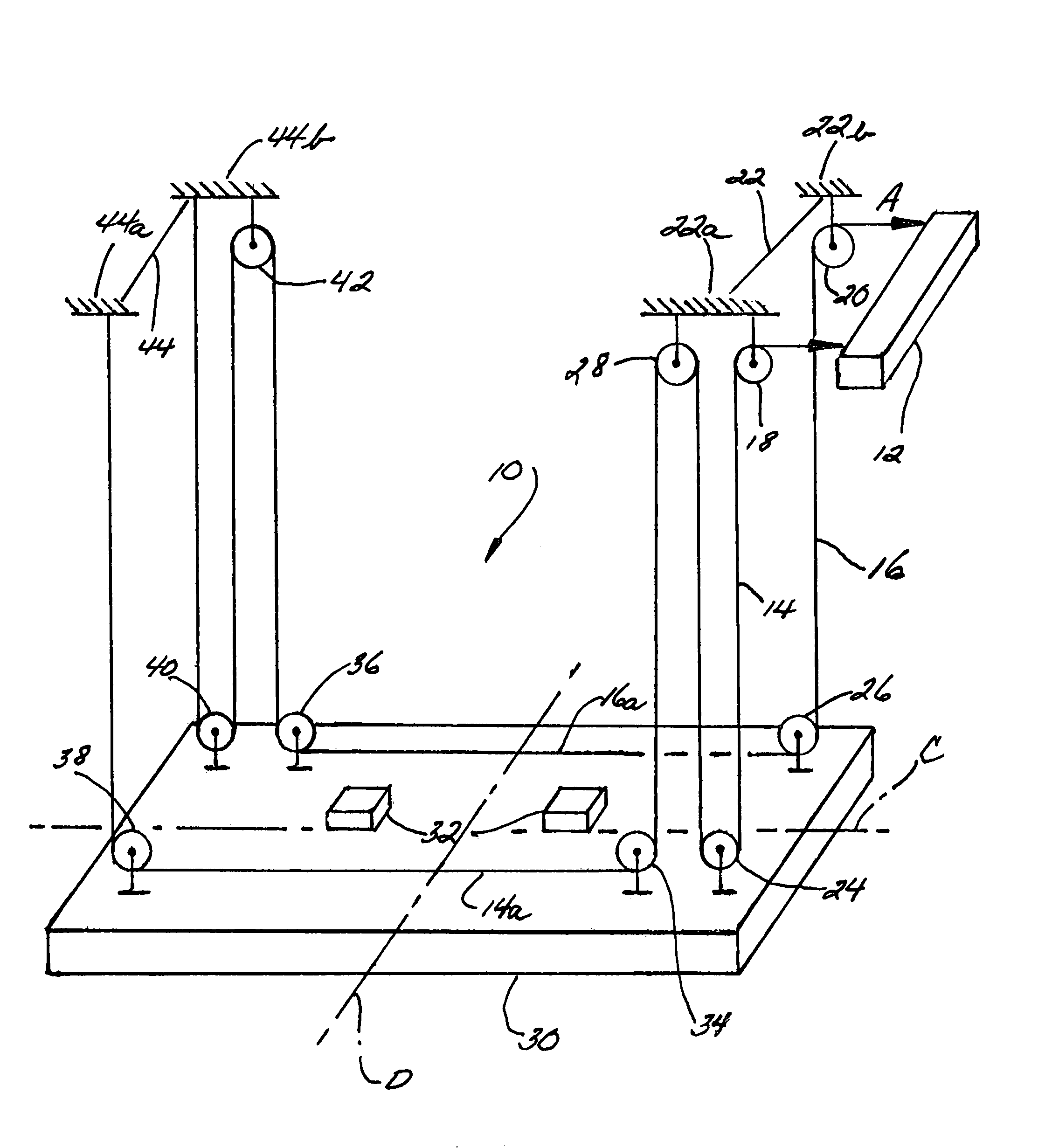
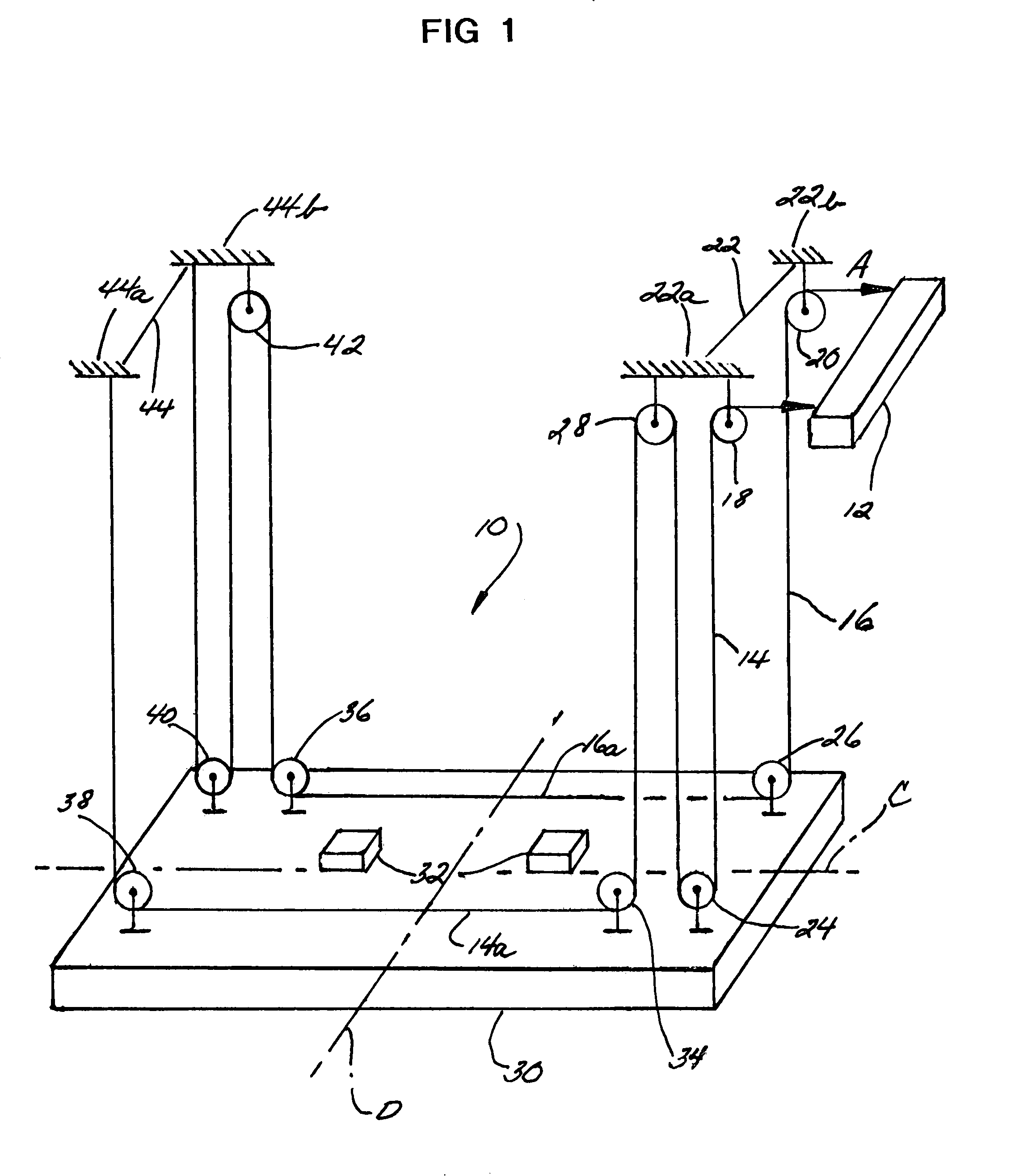
[0026]FIG. 1 illustrates a hoist and suspension or pulley system 10 constructed in accordance with the teachings of the present invention. The pulley system 10 is a typical embodiment of this invention, but it is one of many possible pulley systems that may be constructed as an embodiment of this invention. The system comprises the following elements shown in FIG. 1.[0027](1) two rigid supports 22 and 44 on either side of the load;[0028](2) a rigid beam 30 supporting a load (not shown for clarity) by means of blocks 32 or an equivalent structure fixed to the rigid beam 30;[0029](3) two non-extensible lines 14 and 16;[0030](4) ten pulleys, five on each of the lines of (3);[0031](5) a power source 12 which may be a motor, winch or other device, to which one end of each line of (3) is attached and which draws both lines simultaneously at the same rate.

[0032]These elements (1) through (5) are interconnected and operate as described in the following paragraphs:

[0033]The three pulleys on ...


PUM


Abstract

A load hoisting system for raising and lowering a load. A first line supports a rigid beam with unequal mechanical advantages on either side of the load. A second line supports the same rigid beam with mechanical advantages on either side of the load that are, in total, equal to those on the first line but with a ratio of mechanical advantages unequal to the ratio of mechanical advantages of the first line. One end of each line is fastened to a fixed support and the other ends of the two lines are drawn at the same rate by a power source, which system eliminates all axial rotation of the beam. The system may be applied to both ends of a long load by drawing of all lines in synchronism, advantageously being applied to lift both ends of a boat.

Description

CROSS-REFERENCE TO RELATED APPLICATIONS[0001]Not applicableSTATEMENT REGARDING FEDERALLY SPONSORED RESEARCH OR DEVELOPMENT[0002]Not applicableINCORPORATION-BY-REFERENCE OF MATERIAL SUBMITTED ON A COMPACT DISC[0003]Not applicableBACKGROUND OF THE INVENTION[0004]1. Field of the Invention[0005]This invention relates generally to the field of lifts and more particularly to self-stabilizing hoists and suspension systems such as those for suspending and lowering and lifting watercraft into and from the water.[0006]2. Description of Related Art[0007]Mechanisms for lifting, lowering and suspending large loads have been in use for centuries. In particular, pulley and cable systems are especially useful because they are light, strong, adaptable to many loads and easily powered by a motor or a manually driven winch. In lifting large loads, it is often inconvenient or impossible to provide for cables or structural members that pass overhead across the load. This is particularly true of large lo...

Claims


Application Information

Patent Timeline
IPC IPC(8): B66D1/36
CPCB66D1/26B66C13/08
Inventor BELLANTONI, JOHN F.
Owner BELLANTONI JOHN F
Features
  • Generate Ideas
  • Intellectual Property
  • Life Sciences
  • Materials
  • Tech Scout
  • Unparalleled Data Quality
  • Higher Quality Content
  • 60% Fewer Hallucinations
Learn More