Field-sequential color display unit and display method

a color display unit and field-sequential technology, applied in the field of field-sequential color display units and display methods, can solve the problems of reducing limiting the sub-field frequency, and difficult to provide such a circuit, so as to reduce the color breakup of optional images and increase the sub-field frequency

Inactive Publication Date: 2005-06-28
KK TOSHIBA
View PDF8 Cites 77 Cited by
  • Summary
  • Abstract
  • Description
  • Claims
  • Application Information

AI Technical Summary

Benefits of technology

[0014]It is therefore an object of the present invention to eliminate the aforementioned problems and to provide a field-sequential color display unit and display method capable of reducing the color breakup of an optional image without greatly increasing a sub-field frequency.

Problems solved by technology

This is interference that the profile of an image or screen is seen so as to be colorized since the RGB-images are time-integrated without being coincident with each other on a retina due to the eye movement following a moving picture, blink or saccade of an eye.
Such a phenomenon gives viewing stress or fatigue to the observer when the display unit is watched for a long time.
However, there is a limit of increasing the sub-field frequency due to the response time of a liquid crystal display or the like, and it is difficult to provide such a circuit, so that this is not preferred means.
According to this method, most of signal components are displayed in the W sub-field in the case of an achromatic color components having high luminance, i.e., in the case of displaying a bright and whitish image, so that it is theoretically difficult to recognize color breakup.
However, the aforementioned method can hardly obtain this effect in the case of displaying an image which comprises chromatic color components, e.g., in the case of displaying an image comprises many R and B signals and hardly contains G signals.

Method used


Image

  • Field-sequential color display unit and display method
  • Field-sequential color display unit and display method
  • Field-sequential color display unit and display method

Examples


first embodiment

(First Embodiment)

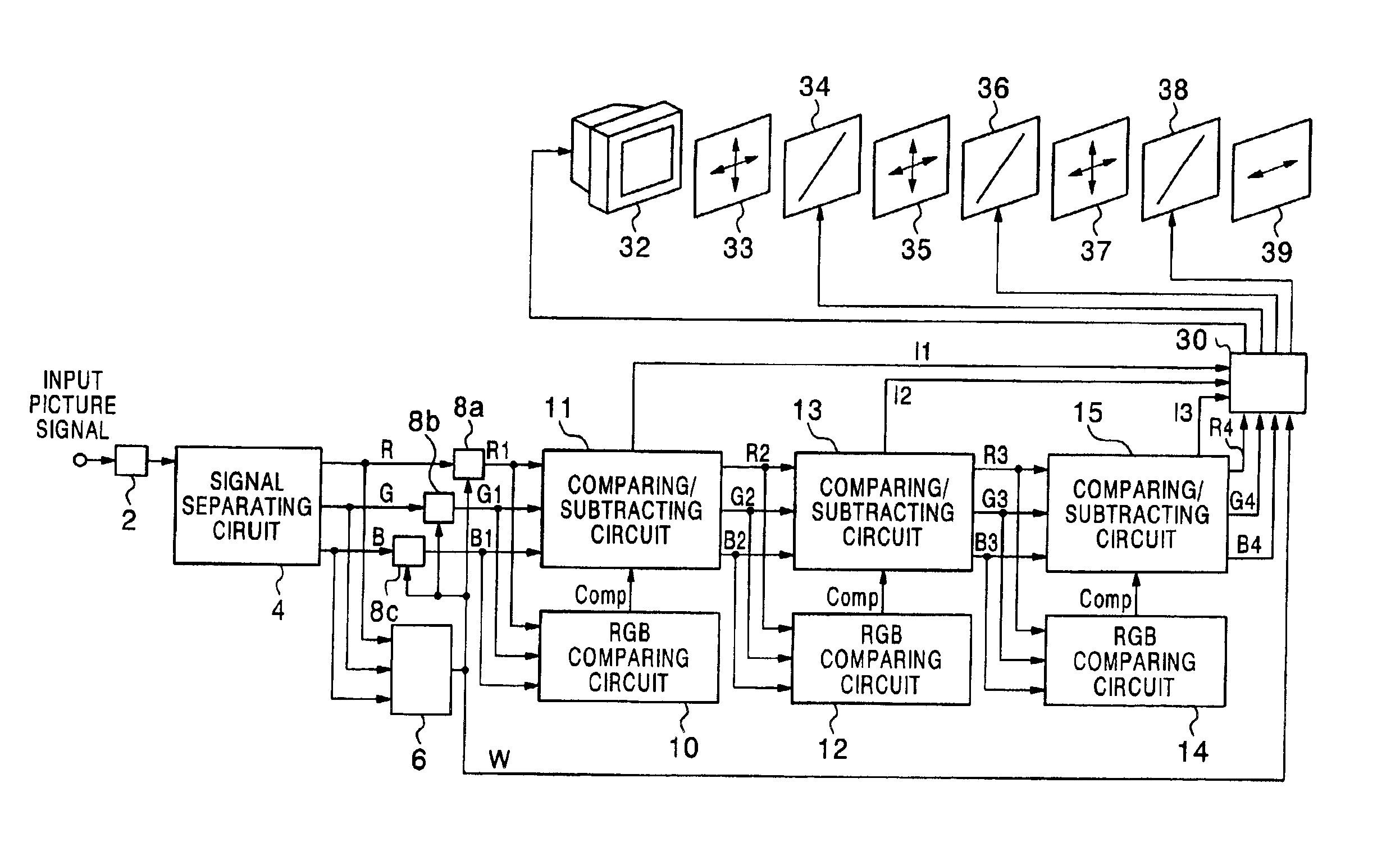
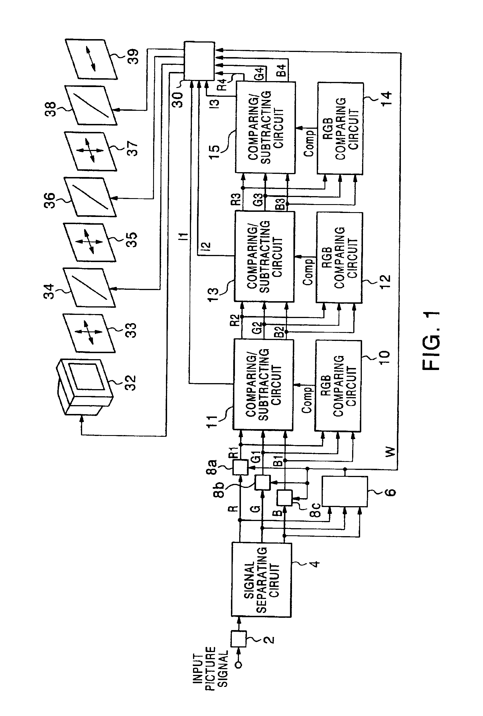
[0066]FIG. 1 shows the construction of a field-sequential color display unit according to the first embodiment of the present invention. The field-sequential color display unit in this embodiment comprises an inverse gamma correction circuit 2, a signal separating circuit 4, an RGB minimum-value detecting circuit 6, subtracting circuits 8a, 8b, 8c, RGB comparing circuits 10, 12, 14, comparing / subtracting circuits 11, 13, 15, a liquid crystal color shutter driving circuit 30 (which will be also hereinafter referred to as an LCCS driving circuit 30), a monochrome CRT 32, chromatic polarizers 33, 35, 37, liquid crystal shutters 34, 36, 38, and an achromatic polarizer 39.

[0067]The construction and operation of the field-sequential color display unit in this embodiment will be described below.

[0068]After an input picture signal is inversely gamma-corrected by the inverse gamma correction circuit 2, it is separated into three-primary color picture signals, i.e., an R sig...

second embodiment

(Second Embodiment)

[0088]FIG. 5 shows the construction of a field-sequential color display unit according to the second embodiment of the present invention. The field-sequential color display unit in this embodiment uses three-primary color signals of R, G and B signals and n non-three-primary color signals for carrying out a field-sequential color display. The field-sequential color display unit comprises an inverse gamma correction circuit 2, a signal separating circuit 4, signal separating circuits 16, 19, signal comparing circuits 17, 20, subtracting circuits 18, 21, an LCCS driving circuit 30, a monochrome CRT 32, chromatic polarizers 33, 35, 37, liquid crystal shutters 34, 36, 38, and an achromatic chromatic polarizing plate 39. In this embodiment, n is 2.

[0089]The construction and operation of the field-sequential color display unit in this embodiment will be described below.

[0090]After an input picture signal is inputted to the inverse gamma correction circuit 2 to be invers...

third embodiment

(Third Embodiment)

[0101]Referring to FIG. 6, a field-sequential color display unit according to the third embodiment of the present invention will be described below.

[0102]The field-sequential color display unit in this embodiment uses R, G, B and W signals and a non-three-primary color signal for carrying out a field-sequential color display, and the construction thereof is shown in FIG. 6. The field-sequential color display unit in this embodiment comprises an inverse gamma correction circuit 2, a signal separating circuit 4, an RGB minimum-value detecting circuit 6, subtracting circuits 8a, 8b, 8c, RGB comparing circuits 10, 12, 14, comparing / subtracting circuits 11, 13, 15, a liquid crystal color shutter driving circuit 30 (which will be also hereinafter referred to as an LCCS driving circuit 30), a monochrome CRT 32, chromatic polarizers 33, 35, 37, liquid crystal shutters 34, 36, 38, and an achromatic polarizer 39. That is, the RGB comparing circuits 12, 14 and the comparing / s...


PUM

PropertyMeasurementUnit
frequencyaaaaaaaaaa
sub-field frequencyaaaaaaaaaa

Abstract

There is provided a field-sequential color displaying method capable of reducing color breakup with respect to an optional image without greatly increasing a sub-field frequency. The field-sequential color display method includes; time-sequentially displaying of luminous information of an input image information with every display color and changing the display color in synchronism with the displaying of the luminous information in order to display the input image information, wherein one frame period in which one color image is displayed includes at least four sub-field periods in which information of each color is displayed, and a picture signal displayed in at least one sub-field period is a non-three-primary color picture signal which is generated from at least two primary color signals of input picture signals including three-primary color signals.

Description

CROSS REFERENCE TO RELATED APPLICATION[0001]This application is based upon and claims the benefit of priority from the prior Japanese Patent Applications No. 2000-389085, filed on Dec. 21, 2000; the entire contents of which are incorporated herein by reference.BACKGROUND OF THE INVENTION[0002]1. Field of the Invention[0003]The present invention generally relates to a field-sequential color display unit and display method.[0004]2. Description of Related Art[0005]Conventionally, typical color displays are designed to carry out a color display on the basis of spatially additive color mixing system. In general, the spatially additive color mixing system is a method for arranging three-primary colors, i.e., red (which will be hereinafter referred to as R), green (which will be hereinafter referred to as G) and blue (which will be hereinafter referred to as B), in parallel so that the observer can not recognize such a state that R, G and B are spatially divided, and the primary colors are...

Claims


Application Information

Patent Timeline
Patent Type & Authority Patents(United States)
IPC IPC(8): G09G5/02G09G3/36G09G3/34H04N9/16H04N9/30H04N9/31H04N9/22H04N9/12G02F1/133G02F1/13G02F1/13357G09F9/00G09G3/20
CPCG02B26/008H04N9/3197G09G3/3413G09G3/36G09G3/3607G09G5/02H04N9/22H04N9/30H04N9/3111H04N9/3114H04N9/3179G02B27/017G02B2027/0112G02B2027/014G09G2310/0235G09G2320/0242G09G2320/0261G09G2320/103G09G2340/06
Inventor BABA, MASAHIROTAIRA, KAZUKIOKUMURA, HARUHIKO
Owner KK TOSHIBA
Why Eureka
Try Eureka