LCD backlight system using light emitting diode chip

a diode chip and backlight technology, applied in the direction of lighting and heating equipment, planar/plate-like light guides, instruments, etc., can solve the problems of inability to meet the slim design requirement, undesirable bright lines, and increase the thickness of the backlight system, so as to enhance the directivity of light emitted and enhance the polarization efficiency

Inactive Publication Date: 2008-08-05
SAMSUNG ELECTRONICS CO LTD
View PDF17 Cites 19 Cited by
  • Summary
  • Abstract
  • Description
  • Claims
  • Application Information

AI Technical Summary

Benefits of technology

[0018]The above backlight system may further include a partial blocking member that partially transmits light that is emitted from the light emitting device which travels in a direction away from the base plate by decreasing the amount of the traveling light.
[0020]The backlight system may further include at least one of a brightness enhancement film to enhance the directivity of light emitted from the transmission diffusion plate and a polarization enhancement film to enhance polarization efficiency.

Problems solved by technology

Accordingly, in order to diffuse the light emitted from the light source more uniformly, it is necessary to increase a distance between the light source and the transmission diffusion plate, which results in an increase in the thickness of the backlight system.
However, when the backlight system is thick, an LCD employing such a backlight system, for instance, an LCD TV, is also thick, thus failing to satisfy a slim design requirement.
When a distance between the lines increases, an undesirable bright line appears.

Method used


Image

  • LCD backlight system using light emitting diode chip
  • LCD backlight system using light emitting diode chip
  • LCD backlight system using light emitting diode chip

Examples


Embodiment Construction

[0036]Reference will now be made in detail to the embodiments of the present general inventive concept, examples of which are illustrated in the accompanying drawings, wherein like reference numerals refer to the like elements throughout. The embodiments are described below in order to explain the present general inventive concept by referring to the figures.

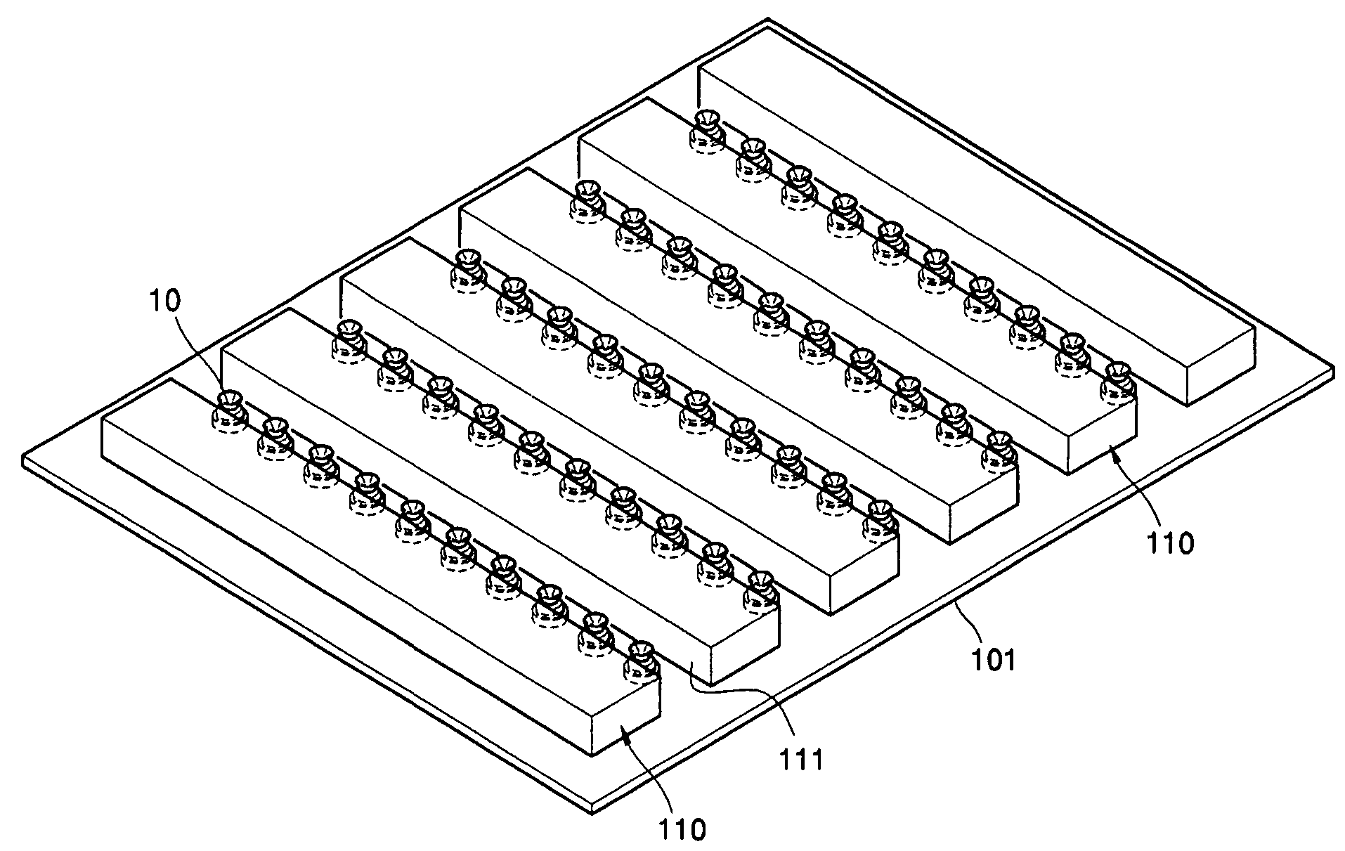
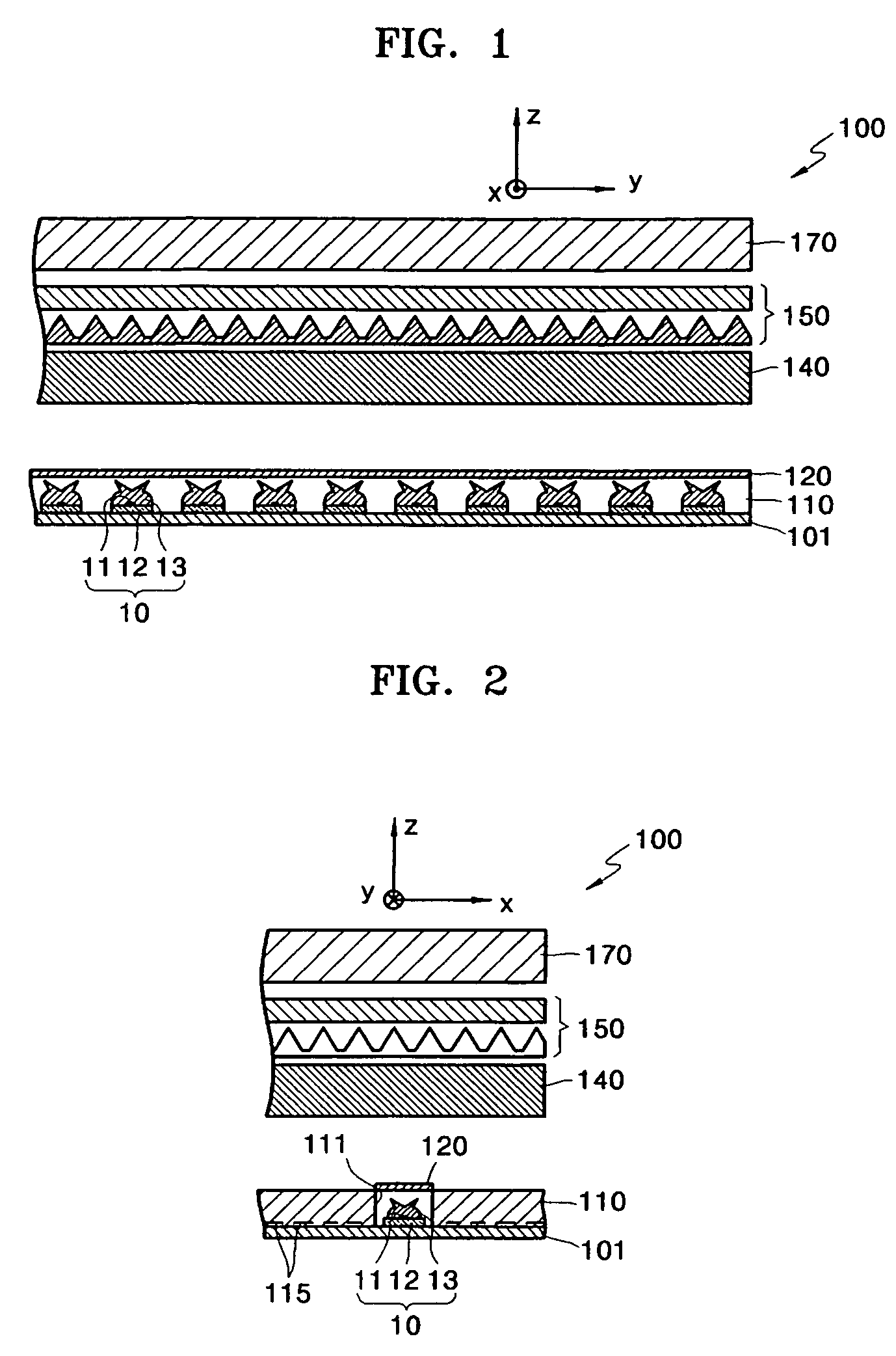
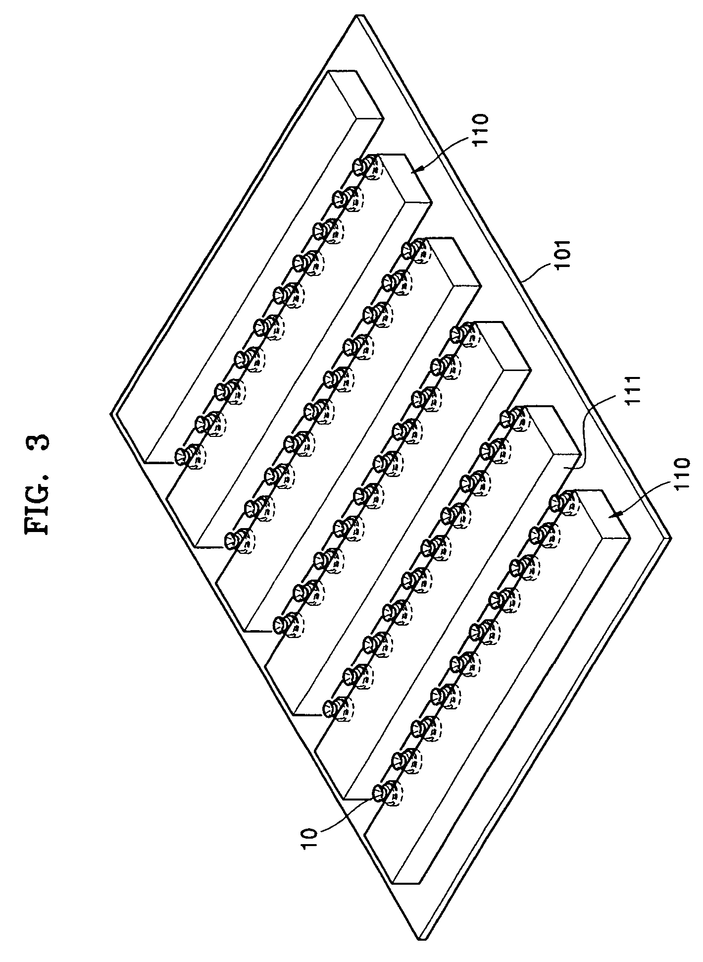
[0037]FIGS. 1 and 2 are schematic sectional views of a backlight system according to an exemplary embodiment of the present general inventive concept, FIG. 3 is a perspective view schematically illustrating an arrangement of a light guide panel and light emitting devices according to an exemplary embodiment of the present general inventive concept, and FIG. 4 is a detailed view of the light emitting device of FIG. 1. Specifically, FIG. 1 is a sectional view taken along a length of a light emitting device and FIG. 2 is a sectional view taken along a direction perpendicular to the length of the light emitting device of FIG. 1.

[003...


PUM


Abstract

A backlight system and an LCD employing the backlight system. The backlight system includes a plurality of light emitting devices arranged on a base plate to form a plurality of lines each including a plurality of light emitting devices, and a light guide panel having a sidewall spaced apart from the plurality of light emitting devices such that light incident from the plurality of light emitting devices is dispersed by inner reflection, and a scattering region formed adjacent to the base plate such that light incident into the scattering region is irregularly reflected to emit in a direction away from the base plate.

Description

CROSS-REFERENCE TO RELATED APPLICATIONS[0001]This application claims the benefit of Korean Patent Application No. 10-2004-0111103, filed on Dec. 23, 2004, in the Korean Intellectual Property Office, the entire contents of which are incorporated herein by reference.BACKGROUND OF THE INVENTION[0002]1. Field of the Invention[0003]The present general inventive concept relates to a backlight system and a liquid crystal display using the same, and more particularly, to a direct light type of backlight system used in a liquid crystal display.[0004]2. Description of the Related Art[0005]A liquid crystal display (LCD), commonly known as one of the types of flat panel display devices, is a passive display that forms an image using incident light from an outside source as opposed to using self luminescence. A backlight system may be used in a LCD device and may be disposed at a rear portion of the LCD to irradiate light toward a liquid crystal panel.[0006]Backlight systems are classified into ...

Claims


Application Information

Patent Timeline
Patent Type & Authority Patents(United States)
IPC IPC(8): F21V7/04G09F13/04H01L33/54H01L33/60
CPCG02B6/003G02B6/0043G02F1/133603G02B6/0061G02B6/0056G02F1/1335
Inventor NOH, JI-WHANJEONG, JIN-GILJUNG, IL-YONG
Owner SAMSUNG ELECTRONICS CO LTD
Why Eureka
Try Eureka