
Capacitive electric musical instrument vibration transducer

a technology of electric musical instruments and vibration transducers, applied in the field of musical instruments, to achieve the effects of reducing costs, reducing costs, and reducing costs

Inactive Publication Date: 2008-08-05
FREITAS PAUL JOHN
View PDF16 Cites 44 Cited by
  • Summary
  • Abstract
  • Description
  • Claims
  • Application Information

AI Technical Summary

Benefits of technology

[0025]Yet another object of the invention is to provide electric musical instrument vibration transducers that can be produced and sold at a lower cost than traditional microphones. By integrating the transducer into acoustic instruments during the manufacturing process, customers can realize cost savings as well as greater reliability, fidelity of signal, application flexibility, and setup simplicity.
[0026]Another object of the invention is to give musicians more signal output options with less equipment than they might otherwise need. For example, guitarists value the sound of both acoustic guitars and electric guitars, even though they sound very different. It is not unusual for a guitarist on a concert tour, for example, to play both types of guitar at different times during a performance. This means that a guitarist must have one of each type of guitar available on stage, which also means packing two separate, bulky instruments, plus all of their associated microphones, instrument cables, amplifiers, and so forth, for the tour. The invention presented here, as shown below, can eliminate the need for a separate, complicated microphone apparatus for acoustic guitars and, at the same time, can be made to give a single acoustic guitar the ability to generate an electric guitar-like signal at the flip of a switch. The increased simplicity and reduction in necessary equipment can be very valuable for traveling musicians with limited assistance and resources.
[0027]One of the most significant objects of the invention is to create a transducer for acoustic instruments that is less sensitive to ambient noise than conventional microphones. The invention will create its output signals from the vibrations of its sound emitting surfaces directly, without using sound as an intermediary, thus blocking a large amount of ambient noise from the output signal. Acoustic musical instruments can respond audibly to ambient noise, as is evident from the phenomenon known as snare buzz, where a snare drum's resonant head buzzes in response to noise from another drum, musical instrument, speaker, or other noise source placed nearby. Still, ambient noise reduction can be significant compared to conventional miking techniques, which can be a valuable effect for musicians and sound engineers.

Problems solved by technology

This means that a guitarist must have one of each type of guitar available on stage, which also means packing two separate, bulky instruments, plus all of their associated microphones, instrument cables, amplifiers, and so forth, for the tour.

Method used


Image

  • Capacitive electric musical instrument vibration transducer
  • Capacitive electric musical instrument vibration transducer
  • Capacitive electric musical instrument vibration transducer

Examples


Embodiment Construction

[0044]Four different embodiments of the invention are described below: a double-headed drum with electric vibration transducer, a cymbal with electric vibration transducer, an acoustic guitar with electric vibration transducer and acoustic / electric signal switch, and a piano with electric vibration transducer. Note that there are many instruments with strong structural similarities to those described below, so the number of instrument types that can benefit from the capacitive electric vibration transducers described here is vast.

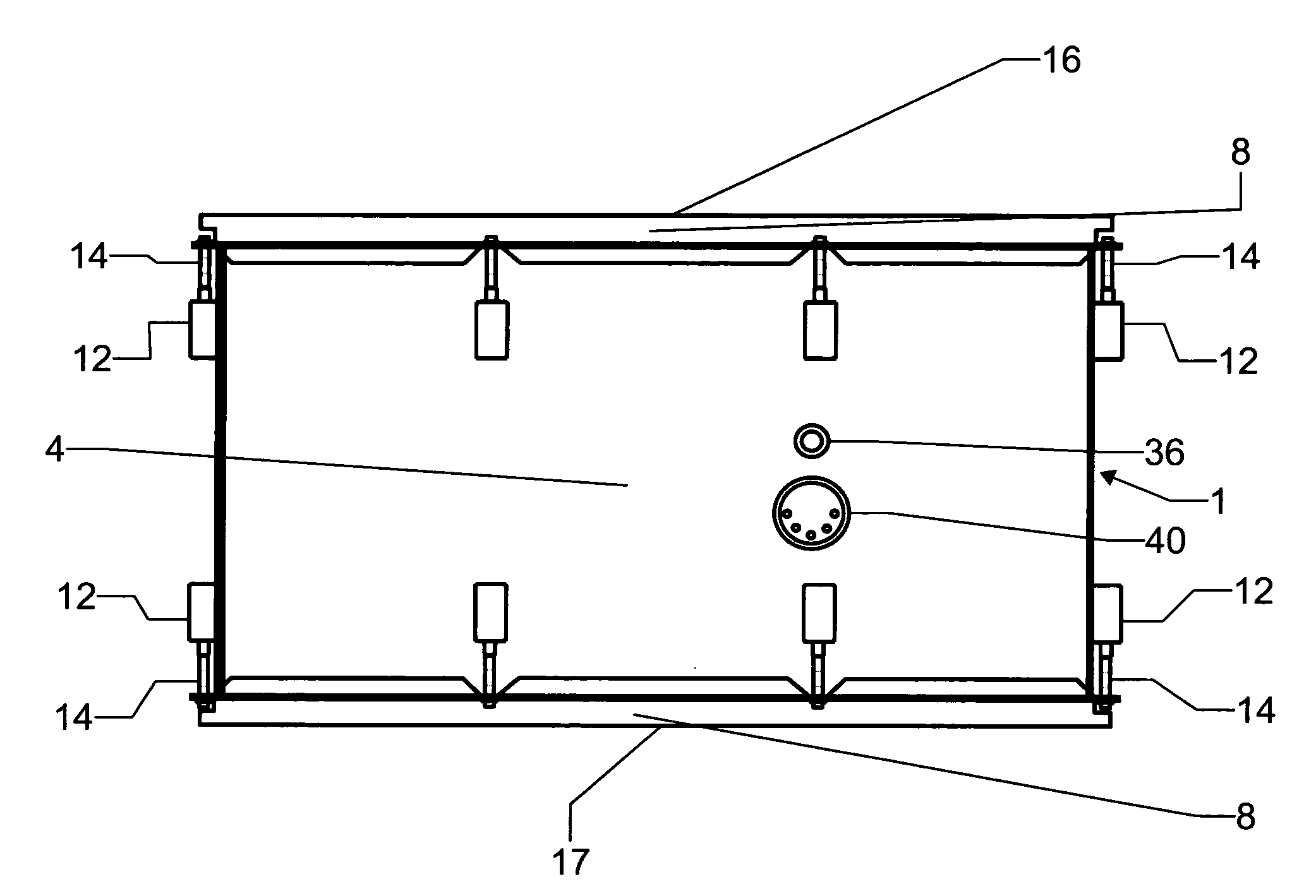
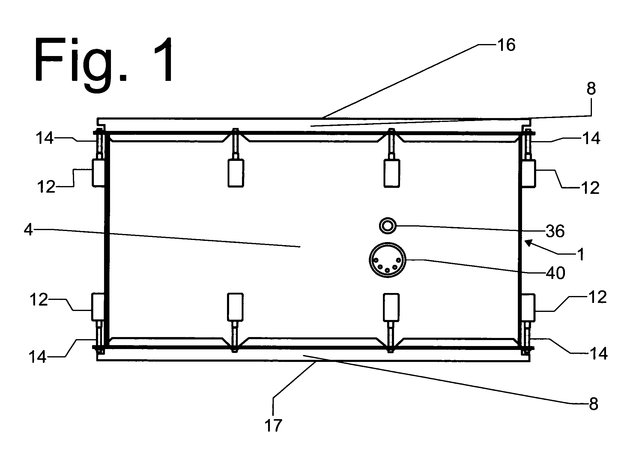
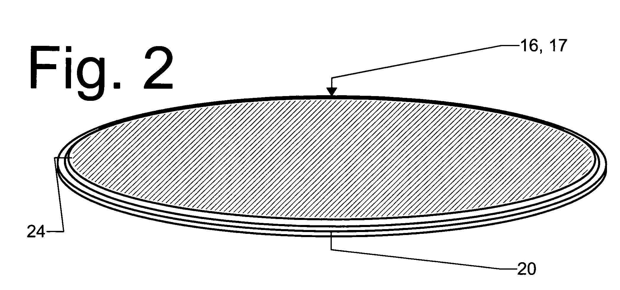
[0045]Referring now to the drawings, FIG. 1 depicts an embodiment of the invention, a double-headed drum with electric transducer 1. It consists of a cylindrical shell assembly 4 capped on top by a batter drumhead assembly 16, and on the bottom by a resonant drumhead assembly 17. In this embodiment, the shell assembly 4 is circular, approximately 12 inches in diameter and 10 inches in depth. The drumhead assemblies 16 and 17 are held taut on the drum by met...


PUM


Abstract

A capacitive electric musical instrument vibration transducer contains one or more parallel plate variable capacitors. Each variable capacitor contains one vibrating variable capacitor plate, an electrically conducting surface that comprises, covers, or is embedded within an acoustically emitting vibrating surface on a musical instrument (such as a drumhead or soundboard), and one fixed variable capacitor plate comprising a rigid electrically conducting surface held a fixed distance away. When the instrument is played, the vibrating surface causes vibrations directly (without using airborne sound as an intermediary) in the vibrating variable capacitor plates, thus causing time-varying voltage oscillations in the parallel plate variable capacitors reflecting the vibrational state, and therefore the sound, of the instrument. An electric circuit in the transducer converts these voltage oscillations into the same kinds of signals produced by microphones and magnetic pickups.

Description

CROSS-REFERENCE TO RELATED APPLICATIONS[0001]This is a continuation of U.S. patent application Ser. No. 10 / 710,782, filed Aug. 2, 2004, now abandoned.BACKGROUND OF INVENTION[0002]This invention relates generally to the field of musical instruments, more particularly to a capacitive electric musical instrument vibration transducers better adapted to interface acoustic musical instruments with electronic recording and amplification equipment. (A musical instrument vibration transducer is sometimes referred to as a pickup, but that term will not be used to refer to the invention presented here to avoid confusion with electric guitar pickups and similar devices which, unlike this invention, are magnetic in nature.) There are three different general categories of musical instruments in common usage at the time of this writing: acoustic, electronic and electric. This invention relates to the first category, and aims to give acoustic instruments many of the advantages of the other instrume...

Claims


Application Information

Patent Timeline
Patent Type & Authority Patents(United States)
IPC IPC(8): G10H3/00
CPCG10H3/12G10H3/10
Inventor FREITAS, PAUL JOHN
Owner FREITAS PAUL JOHN
Learn More