Sensor for measuring moisture and salinity

Active Publication Date: 2008-08-05
GREEN BADGE LTD LIABILITY CORP +1
View PDF7 Cites 16 Cited by
  • Summary
  • Abstract
  • Description
  • Claims
  • Application Information

AI Technical Summary

Benefits of technology

[0023]Returning to the AC meter embodiment used in the sensor of the present invention, it should be noted that the biasing that has been added dramatically improves the detector performance. The presence of the bias voltage allows the detector output to be measured in the absence of any AC signal being present in the circuit. This allows the sensors to be “tared” and captures the variation in components in the detector and temperature drifts. It is not possible to do this with the sensor of the '104 patent. In the calculations above, the readings of the detectors with no signal p

Problems solved by technology

The difficulty with such a sensor scheme is that the calculations to determine Cs and Rs are very complex relations of two ratios: (1) AC Meter 3/AC Meter 1 and (2) AC Meter 2/AC Meter 1.
These calculations are particularly complex in actual systems with higher order effects present, thus requiring the use of complex number equations.
A further difficulty is that AC meters that operate at such high frequencies are difficult and expensive.
Diode detectors, however, become highly non-linear when the AC voltage lowers to around 0.2 volts such that it becomes difficult to relate the DC meter voltage reading to the actual AC voltage level being measured.
Further, the diode detectors display a significant temperature

Method used


Image

  • Sensor for measuring moisture and salinity
  • Sensor for measuring moisture and salinity
  • Sensor for measuring moisture and salinity

Examples


Embodiment Construction

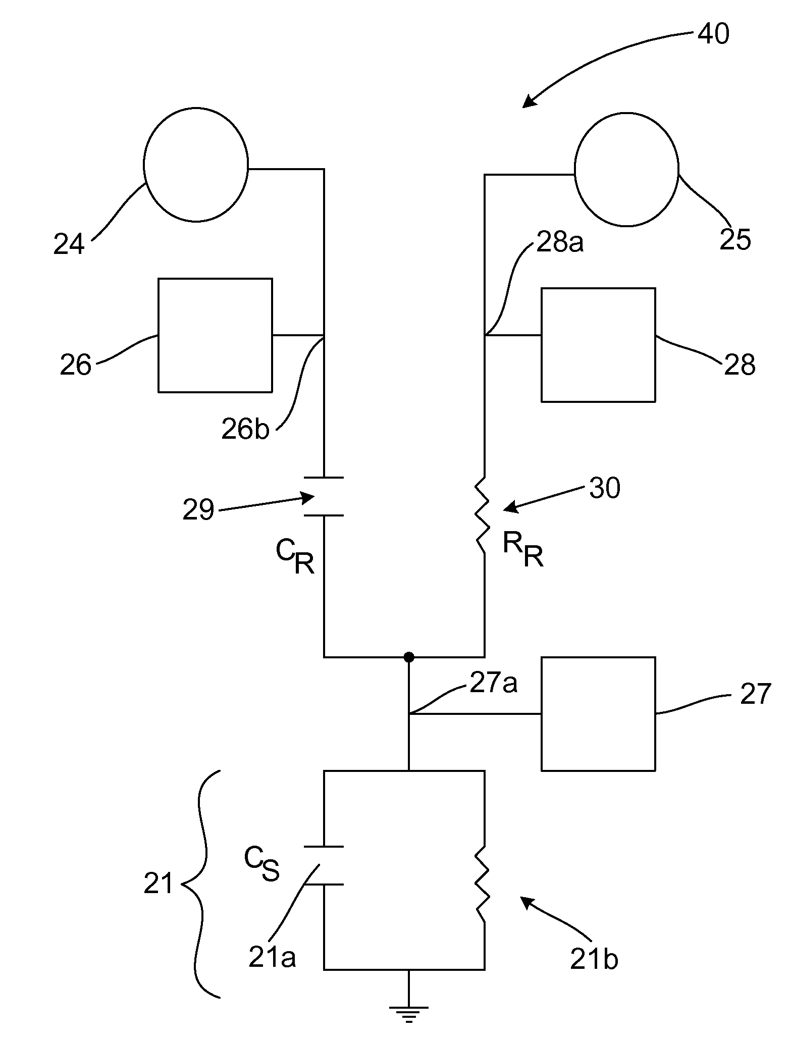
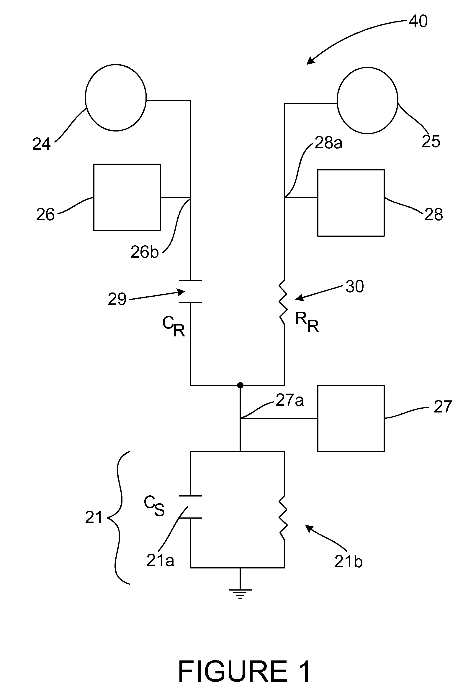
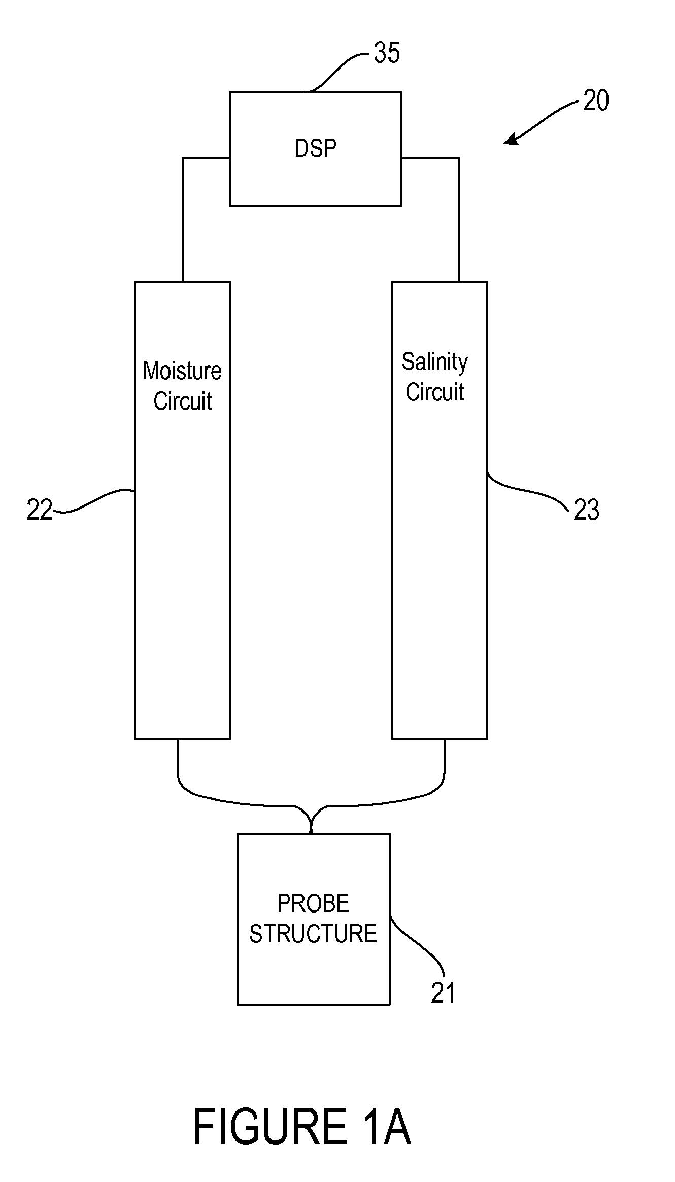
[0038]FIG. 1 illustrates a circuit diagram of a preferred embodiment of the circuit 40 of the sensor apparatus 20 of the present invention. FIG. 2 illustrates a detailed circuit diagram of a preferred section of the circuit 40. FIG. 1A is a block diagram of the sensor apparatus 20. As shown in FIG. 1A, the sensor apparatus 20 preferable includes a digital signal processor 35 connected to a moisture circuit 22 and a salinity circuit 23, which are both connected to a probe structure 21.

[0039]The probe structure 21 is placed in the soil which is to be measured. The probe structure 21 forms an effective coaxial capacitor within the soil. Such probe structures are well known in the art, and typically include a base and elongated conductors extending from the base and disposed around a central elongated conductor. The digital signal processor 35 or microprocessor, facilitates the process, allowing for multiple conducting structures to be inserted into the soil (or other media of interest)...


PUM


Abstract

A sensor for measuring the moisture and salinity of a material is disclosed herein. The sensor preferably includes a soil moisture circuit, a soil salinity circuit and a probe structure. The soil moisture circuit includes a high frequency oscillator, a voltage meter and a reference capacitor. The soil salinity circuit includes a low frequency oscillator, a voltage meter and a reference resistor. A third voltage meter allows for voltage outputs to be measured to calculate soil moisture and soil salinity values.

Description

CROSS REFERENCE TO RELATED APPLICATION[0001]Not ApplicableSTATEMENT REGARDING FEDERALLY SPONSORED RESEARCH OR DEVELOPMENT[0002]Not ApplicableBACKGROUND OF THE INVENTION[0003]1. Field of the Invention[0004]The present invention related to a sensor for measuring the moisture content and salinity of a material. More specifically, the present invention relates to a sensor for measuring the moisture content and salinity of soil.[0005]2. Description of the Related Art[0006]The prior art discusses several soil monitoring sensors.[0007]There have been several sensor approaches to measuring the moisture and salinity of soil. One such approach is described by U.S. Pat. No. 5,479,104 (the '104 patent). The sensor of the '104 patent uses one oscillator and one frequency, a bridge type scheme with two resistors functioning as reference bridge elements, and three AC meters to measure the unknown capacitance of the soil (Cs) and resistance of the soil (Rs), where the capacitance can be directly re...

Claims


Application Information

Patent Timeline
IPC IPC(8): G01R27/26G01R27/08
CPCG01N33/246G01N27/223
Inventor CAMPBELL, JEFFREY
Owner GREEN BADGE LTD LIABILITY CORP
Why Eureka
Try Eureka