Time synchronization system and method for synchronizing locating units within a communication system using a known external signal

a time synchronization and communication system technology, applied in multiplex communication, synchronisation arrangement, instruments, etc., can solve the problems of different propagation delays in inbound and outbound traffic, the obvious disadvantage of dedicated cabling, and the inability to achieve highly accurate time synchronization

Active Publication Date: 2008-08-12
KEYSIGHT TECH
View PDF16 Cites 28 Cited by
  • Summary
  • Abstract
  • Description
  • Claims
  • Application Information

AI Technical Summary

Benefits of technology

[0007]Embodiments of the present invention provide a time synchronization system for synchronizing local clocks of locating units within a communication system using a known external signal. Each of the locating units receives a radio frequency (RF) signal from a transmitter at a known geographical location and measures the RF signal to produce a respective measurement of the received RF signal and a respective timestamp of the measurement recorded at substantially the same time of each of the local clocks of the locating units. A controller determines a measured time difference of arrival between the locating units using the timestamps and measurements, computes a time synchronization error between the locating units from a difference between the measured time difference of arrival and an expected time difference of arrival and provides a respective time adjustment to each of the locating units to offset the time synchronization error.
[0009]Embodiments of the present invention further provide a method for synchronizing locating units within a communication system. The method includes receiving, from two or more locating units, respective measurements of a radio frequency (RF) signal transmitted from a transmitter at a known geographical location and respective timestamps of the measurements recorded at the locating units. Each measurement is recorded at substantially the same time of a respective local clock of the locating units. The method further includes determining a measured time difference of arrival between the locating units using the timestamps and the measurements, computing a time synchronization error between the locating units from a difference between the measured time difference of arrival and an expected time difference of arrival and providing a respective time adjustment to each of the locating units to offset the time synchronization error.

Problems solved by technology

However, using dedicated cabling presents the obvious disadvantage of purchasing and installing the dedicated cabling, especially when the locating units are geographically distant from one another.
In addition, highly accurate time synchronization may not be possible when using a network with multiple switches and / or routers between the locating units.
For example, when using a T1 / E1 link with multiple switches / routers, inbound signals may traverse a different path from outbound signals, thereby producing different propagation delays in inbound and outbound traffic.
Furthermore, although GPS enables highly accurate time synchronization, GPS requires each locating unit to include an expensive GPS receiver, which may be cost-prohibitive.
In addition, GPS only works in areas where the GPS receiver has access to a sufficient number of GPS satellites.
For example, GPS synchronization may not be possible for locating units that are located in remote areas, in the interior of a building or underground.

Method used


Image

  • Time synchronization system and method for synchronizing locating units within a communication system using a known external signal
  • Time synchronization system and method for synchronizing locating units within a communication system using a known external signal
  • Time synchronization system and method for synchronizing locating units within a communication system using a known external signal

Examples


Embodiment Construction

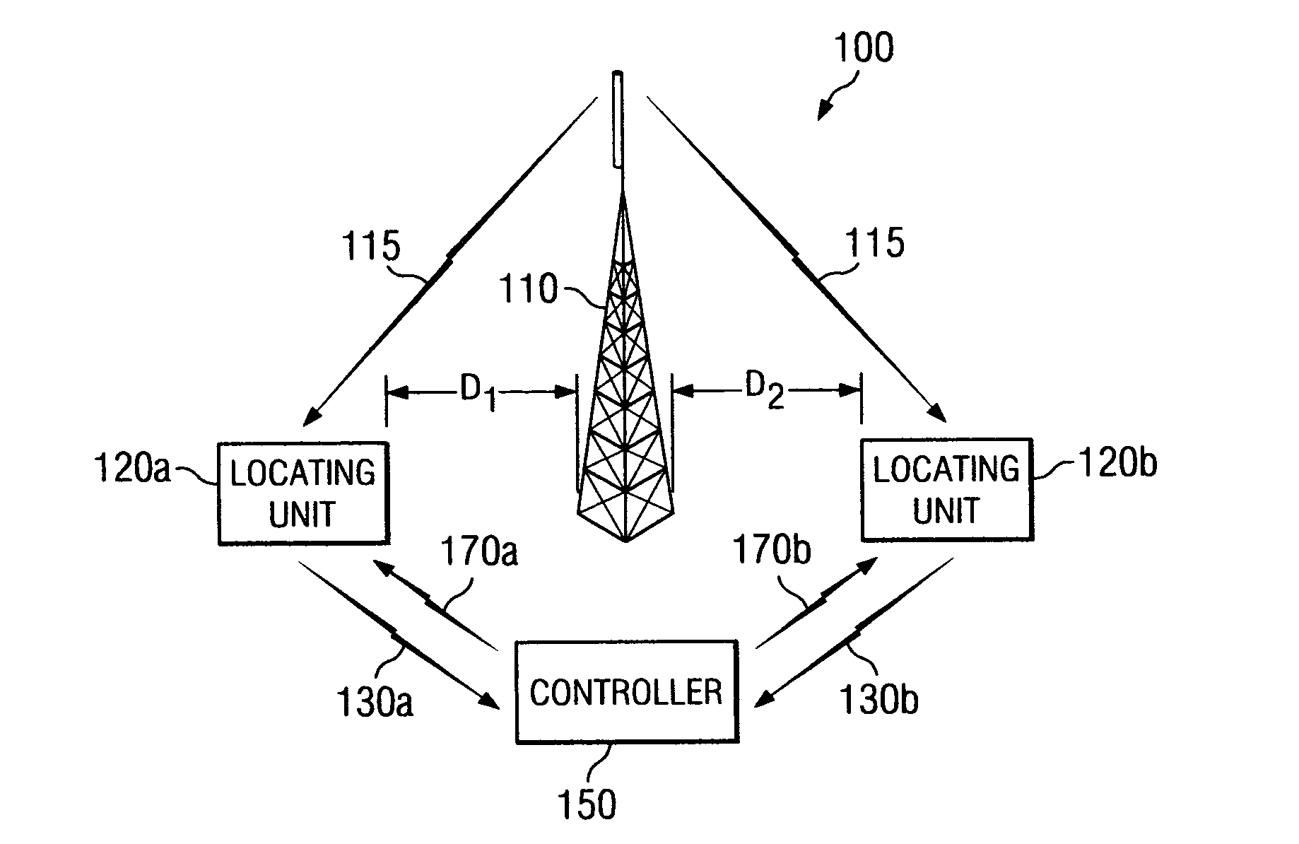
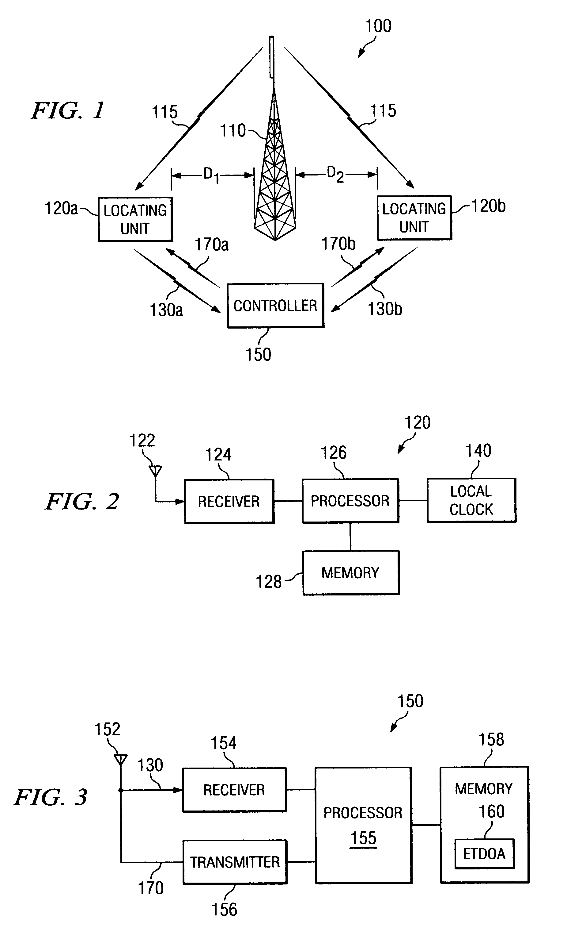
[0017]FIG. 1 is a schematic block diagram illustrating an exemplary and simplified time synchronization system 100. The time synchronization system 100 includes a transmitter 110, two or more locating units 120a and 120b and a controller 150. The locating units 120a and 120b form at least a part of a radio communication system. For example, the radio communication system may include a series of receivers located within an area networked (e.g., via the Internet) together with the controller 150. In an exemplary embodiment, the locating units 120a and 120b operate in a signal reception mode to locate radio devices (not shown) within the radio communication system using a time difference of arrival (TDOA) positioning method. One example of a radio device is a cellular telephone.

[0018]The transmitter 110 and the locating units 120a and 120b are positioned within the time synchronization system 100 at known geographical locations, which may be fixed or variable. In embodiments where the ...


PUM


Abstract

A time synchronization system synchronizes local clocks of locating units within a communication system using a known external signal. Each of the locating units receives a radio frequency (RF) signal from a transmitter at a known geographical location and measures the RF signal to produce a respective measurement of the signal and a respective timestamp of the measurement recorded at substantially the same time of the local clocks of the locating units. A controller determines a measured time difference of arrival between the locating units using the measurements and timestamps, computes a time synchronization error between the locating units from a difference between the measured time difference of arrival and an expected time difference of arrival and provides a respective time adjustment to each of the locating units to offset the time synchronization error.

Description

BACKGROUND OF THE INVENTION[0001]There are a number of techniques currently available to determine the geographical location of a radio device within a radio communication system. One technique of positioning a radio device is the time difference of arrival (TDOA) method. TDOA systems operate by placing locating units at geographically disbursed locations within a coverage area of the locating devices. The locating units may be stand-alone units or may be integrated with a base station of a wireless telephone network. For example, the coverage area may include a portion of a wide area wireless network or a portion of a local area wireless network.[0002]The locating units operate in either a signal reception mode to receive a signal from the radio device or in a signal transmission mode to transmit a signal to the radio device. When the locating units are configured to receive a signal transmitted from the radio device, each locating unit timestamps the reception of the signal. The d...

Claims


Application Information

Patent Timeline
Patent Type & Authority Patents(United States)
IPC IPC(8): H04J3/06G01S19/11G04G5/00G04R20/00G04R20/22H04W56/00H04W64/00
CPCG01S5/10G01S5/021G01S1/022
Inventor GUILFORD, JOHN H.
Owner KEYSIGHT TECH
Why Eureka
Try Eureka