Pattern sequence synchronization

a pattern sequence and sequence synchronization technology, applied in the direction of synchronisation signal speed/phase control, multi-frequency code system, amplitude demodulation, etc., can solve the problem of analog stages of the transceiver system, carrier-frequency mismatch of the transmitter/receiver, and the usual expectation of extended mismatch, so as to increase the tolerable range of carrier-frequency mismatch

Inactive Publication Date: 2008-08-12
WSOU INVESTMENTS LLC
View PDF13 Cites 2 Cited by
  • Summary
  • Abstract
  • Description
  • Claims
  • Application Information

AI Technical Summary

Benefits of technology

[0016]It is therefore an object of certain embodiments of the present invention to increase the tolerable range of carrier-frequency mismatch.
[0018]Certain embodiments of the present invention use differential phase information, commonly included in a pattern sequence of symbols for correlation. Compared with related art techniques, the following advantages may be achieved:
[0019]at a digital receiver input, a much higher carrier-frequency mismatch is generally tolerable, up to which the pilot detection is able to work;

Problems solved by technology

One of the major errors is the transmitter / receiver carrier-frequency mismatch.
The analog stages of a transceiver system typically introduce unwanted imperfections such as, but not limited to, transmitter / receiver carrier-frequency and / or phase mismatch.
For example, during the system start-up process, an extended mismatch is usually expected.
Finally, the impact of the carrier frequency mismatch usually distorts the correlation result significantly.
Furthermore, frame-dependent working blocks, as well as detection blocks, which usually work on reference and / or received pilot symbols, will commonly not get the necessary inputs.
In other words, if the conventional frame synchronization method is used, the digital receiver is commonly unable to start-up above a threshold of mismatch.
The related art correlation-based frame synchronization techniques typically tolerate this carrier-frequency offset only up to a certain limit, since the impact of the carrier frequency mismatch normally distorts the correlation result significantly.

Method used


Image

  • Pattern sequence synchronization
  • Pattern sequence synchronization
  • Pattern sequence synchronization

Examples


Embodiment Construction

)

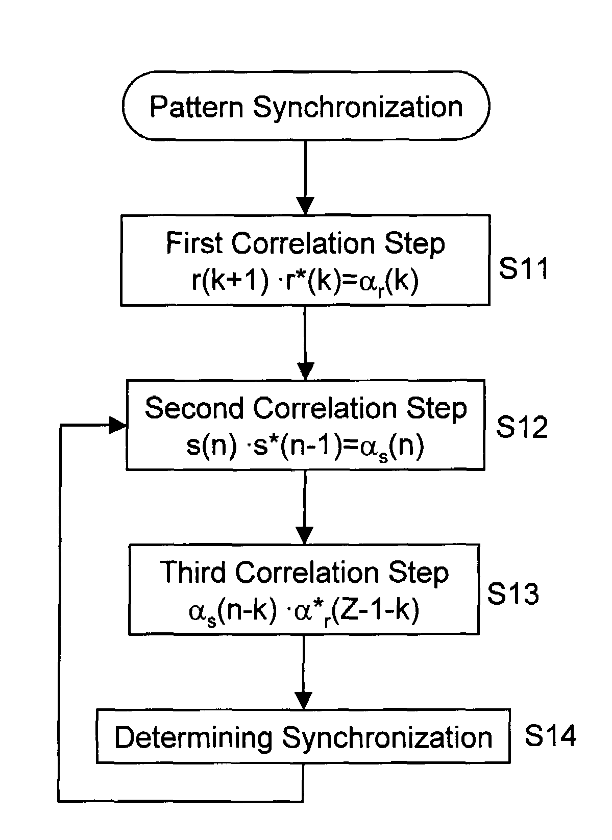
[0041]FIG. 1 shows a flow diagram illustrating a representative method of synchronizing a first pattern sequence and a second pattern sequence according to certain embodiments of the present invention. In step S11, symbols r(k)=rI(k)+jrQ(k) of a first pattern sequence are correlated, which first correlation step yields a first differential phase information sequence αr(k). In step S21, symbols s(n)=sI(n)+jsQ(n) of a second pattern sequence are correlated, which second correlation step yields a second differential phase information sequence αs(n). In step S13, the first and second differential phase information sequences are correlated, which third correlation step yields a correlation result corrDPV(n). Then, in step S14, a synchronization between the first and second pattern sequences is determined, usually on the basis of the obtained correlation result.

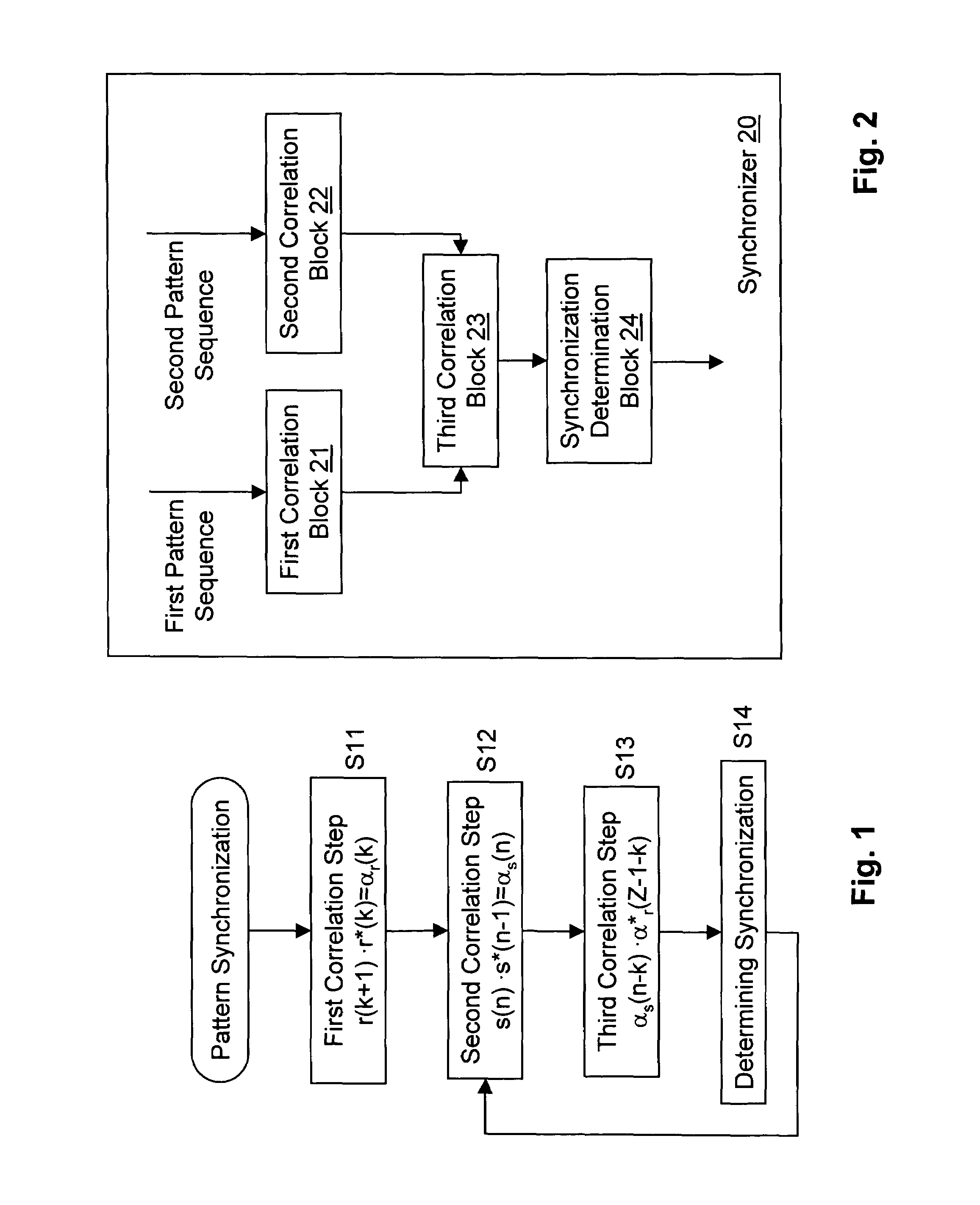
[0042]FIG. 2 shows a block diagram illustrating a commonly used synchronizer 20, commonly for synchronizing two pattern sequence...


PUM


Abstract

A synchronization that includes a pattern sequence. In the synchronization, symbols of a first pattern sequence are usually correlated, the symbols commonly including amplitude and / or phase information, thereby routinely obtaining a first differential phase information sequence, symbols of a second pattern sequence are correlated, the symbols generally including amplitude and / or phase information, thereby typically obtaining a second differential phase information sequence, and then the first and second differential phase information sequences are usually correlated, thereby obtaining a correlation result. Then, a synchronization between the first and second pattern sequences is often determined on the basis of the obtained correlation result.

Description

BACKGROUND OF THE INVENTION[0001]1. Field of the Invention[0002]The present specification relates generally to a method and an apparatus for pattern sequence synchronization between a first and a second pattern sequence. Certain embodiments discussed in the present specification relate to a synchronization between a received pattern sequence which may, for example, be generated at a transmitting device and a reference pattern sequence of a receiving device. Certain embodiments are applicable in single carrier transceivers with frame synchronization for pilot detection, in single carrier quadrature direct conversion transceivers for single carrier detection, and / or in OFDM (Orthogonal Frequency Division Multiplexing) systems for finding training sequences.[0003]2. Description of the Related Art[0004]Frame synchronization is often used to enable further blocks and / or error correction loops in a receiver chain. The reference pattern sequence, usually known at the receiver and typically...

Claims


Application Information

Patent Timeline
Patent Type & Authority Patents(United States)
IPC IPC(8): H04L27/06H04L5/12H04L27/00H04L27/26
CPCH04L5/12H04L27/0014H04L27/2656H04L27/2679H04L2027/0095H04L7/04H04L7/06H04L7/02
Inventor BOTHE, HARALDGASCHLER, DIRK
Owner WSOU INVESTMENTS LLC
Why Eureka
Try Eureka