Workflow defining system and workflow managing system

a workflow and workflow technology, applied in the field of workflow defining and managing system, can solve the problems of inconvenient debugging operation, inability to report to the manager, and inability to achieve the debugging operation procedure smoothly, so as to achieve the effect of easy revision of workflow and effective control of work or data

Active Publication Date: 2008-08-12
VIA TECH INC
View PDF28 Cites 6 Cited by
  • Summary
  • Abstract
  • Description
  • Claims
  • Application Information

AI Technical Summary

Benefits of technology

[0014]In view of the above, the invention directs to a workflow defining system and a workflow managing system that can establish and utilize a workflow to effectively control the progress of work and data.
[0017]Since the workflow defining system and the workflow managing system according to the invention set different terminal states to control the workflow, and each terminal state is designed to have at least one instruction having a corresponding path, the progress of work or data can be controlled effectively. Furthermore, the workflow defining system and the workflow managing system according to the invention can revise the workflow easily by adding and deleting the instructions at the terminal states with the original terminal states remain unchanged. Therefore, the data can be integrated without any data loss.

Problems solved by technology

The above-mentioned workflow, however, is not suitable for many reasons when being implemented practically.
For example, the debug engineer cannot report to the manager when the debug request form is wrong or when the bug-related data is insufficient.
This results in that the debug operation procedure could not be finished smoothly.
In addition, when the debug engineer finishes the debug operation procedure, the correctness of the debug operation cannot be confirmed effectively.
The actions required are difficult and complicated.
Furthermore, after the workflow being revised, since the procedures are different, old data often becomes incompatible with new workflow, which results in the missing of the old data when one must start the new workflow and abandon the old one in the middle of the debug operation procedure.

Method used


Image

  • Workflow defining system and workflow managing system
  • Workflow defining system and workflow managing system
  • Workflow defining system and workflow managing system

Examples


Embodiment Construction

[0027]The workflow defining system and the workflow managing system according to the embodiments of the invention will be described below with reference to relevant drawings, wherein the same elements are assigned with the same reference numbers.

[0028]Please refer to FIG. 3, the workflow defining system 3 according to an embodiment of the invention comprises a state setting module 31, an instruction generating module 32, a path generating module 33, a path altering module 34, and a path deleting module 35. Herein, the state setting module 31, the instruction generating module 32, and the path generating module 33 are necessary, but the path altering module 34 and a path deleting module 35 are optional.

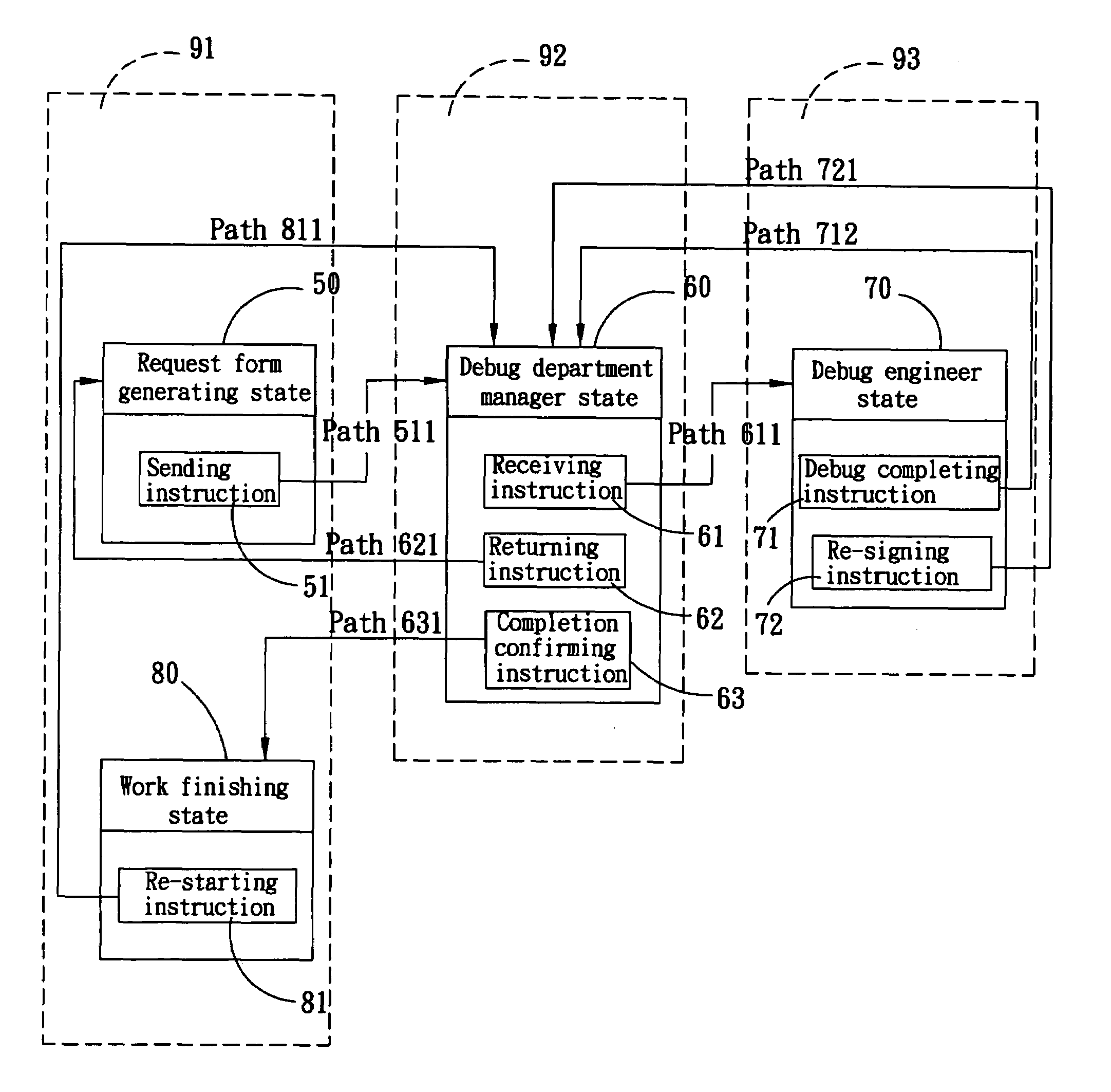
[0029]The state setting module 31 sets at least a first terminal state 41, a second terminal state 42, and a third terminal state 43 (as shown in FIG. 4A).

[0030]The instruction generating module 32 at least generates a first instruction 411, a second instruction 421, and a third instru...


PUM


Abstract

A workflow defining system comprises a state setting module, an instruction generating module, and a path generating module. The state setting module sets at least a first terminal state, a second terminal state, and a third terminal state. The instruction generating module generates a first instruction, a second instruction, and a third instruction respectively corresponding to the first, second, and third terminal states. The path generating module generates a first path, a second path, and a third path respectively according to the first, second, and third instructions. The first path according to the first instruction points to one of the first, second, and third terminal states. The second path according to the second instruction points to one of the first, second, and third terminal states. The third path according to the third instruction points to one of the first, second, and third terminal states. Furthermore, a workflow managing system is disclosed, and performs workflow management according to a workflow defined by the workflow defining system.

Description

BACKGROUND OF THE INVENTION[0001]1. Field of Invention[0002]The invention relates to a workflow defining and managing system and, in particular, to a workflow defining and managing system that is capable of establishing flowcharts to control the progress of work or data.[0003]2. Related Art[0004]To improve the work efficiency and to integrate the operation procedures of different departments, one usually designs a workflow to link up all operation procedures in view of actual needs. Then, a flowchart is established for different departments, so that they can execute and control their operation procedures according to this flowchart.[0005]A conventional flowchart for debug operation procedure will be described below with reference to FIG. 1A. As shown in FIG. 1A, a debug report generating department firstly collects bug-related data and forwards them to the manager of a debug department (step S01). In this step, for example, bug-related data could come from the customer service depar...

Claims


Application Information

Patent Timeline
Patent Type & Authority Patents(United States)
IPC IPC(8): G06F9/44G06Q10/00
CPCG06Q10/06
Inventor LIANG, CHIA-YICHEN, ANDY
Owner VIA TECH INC
Why Eureka
Try Eureka