
Method for monitoring tyre deformations and monitoring system therefor

Inactive Publication Date: 2008-08-19
PIRELLI TYRE SPA
View PDF12 Cites 12 Cited by
  • Summary
  • Abstract
  • Description
  • Claims
  • Application Information

AI Technical Summary

Benefits of technology

[0015]Applicant perceived that the need for a method and system for monitoring the deformations of a tyre being sensitive; and reliable, thus capable of detecting even small deformations, advantageously in the three spatial directions, was still felt. Also, such a system and method should be simple and easy to be manufactured / performed.
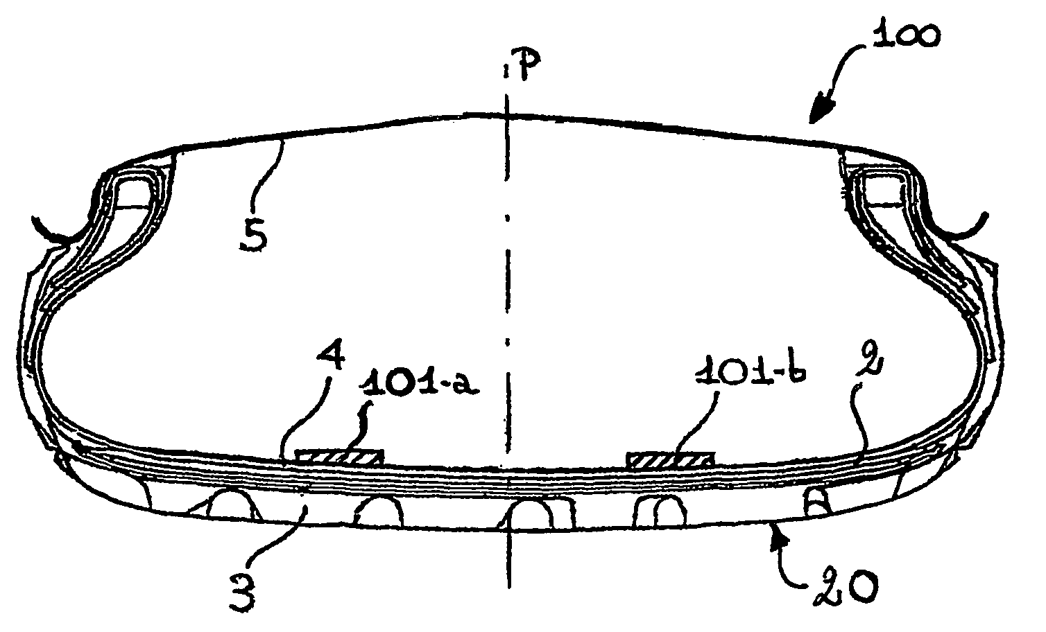
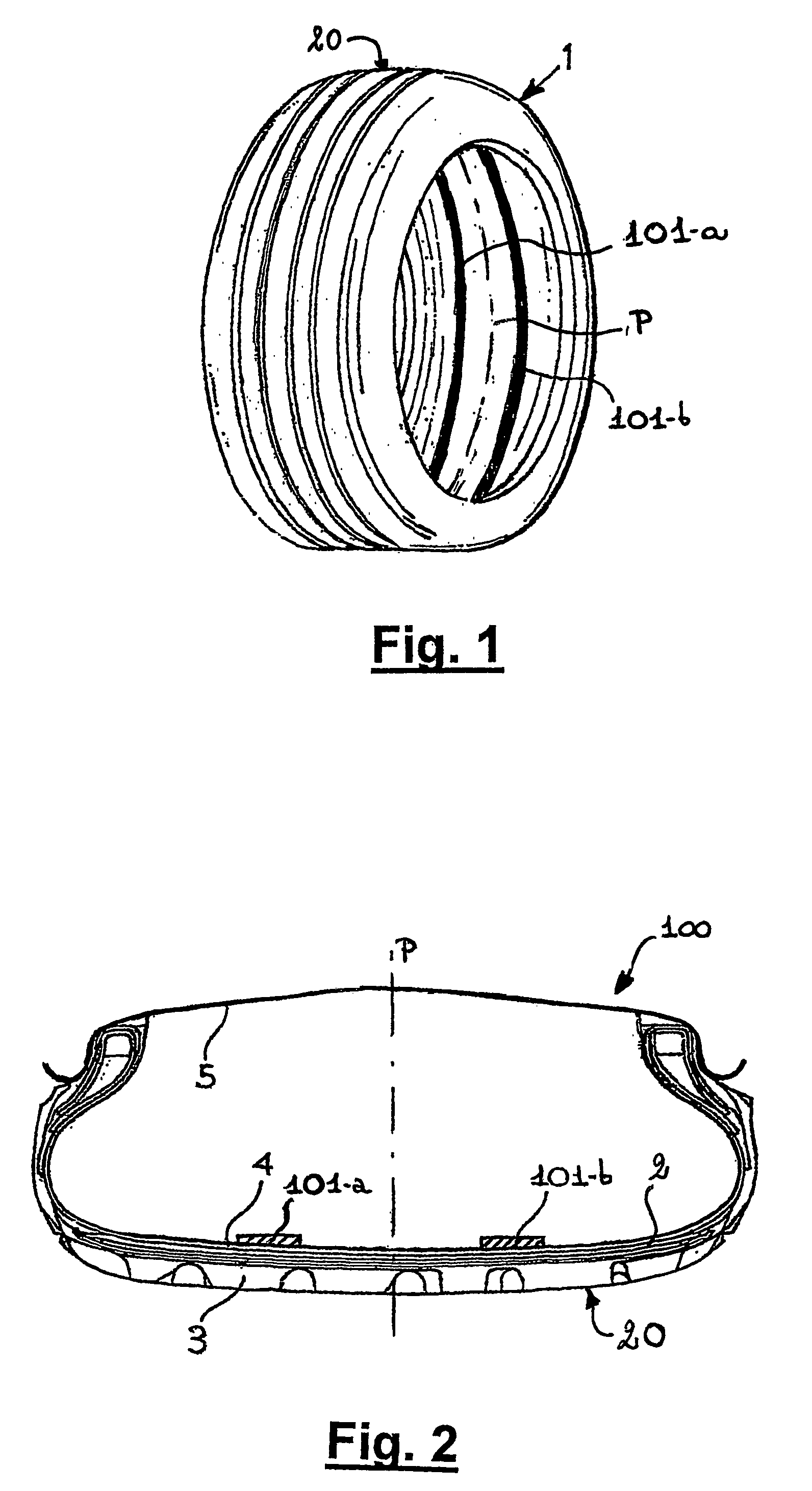
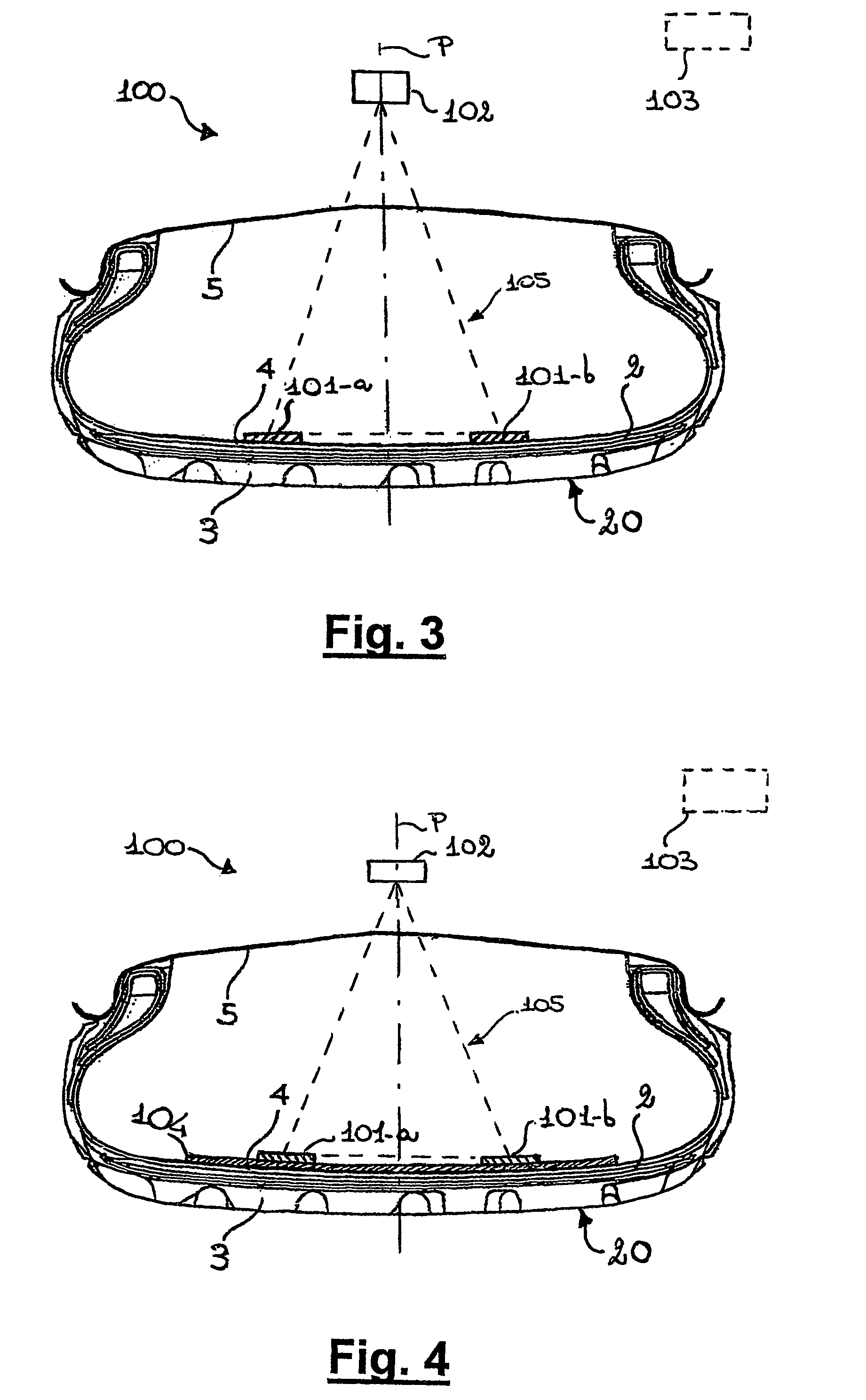
[0028]The detection sensitivity is higher and more reliable than that of the known systems in view of various features, for example, the mutual positioning of the at least two emitters of magnetic field and the at least one main sensor, said positioning being substantially triangular. Such positioning yields a composite magnetic field distributions varying in the three spatial directions around the space portion where the main sensor is substantially located. Also, variations of the MF components are expressed by simple linear or quadratic laws as a function of the relative displacement of at least one of the at least two MF emitters, which is caused by the tyre deformation. Hence, the deformations can be effectively monitored in one or, preferably, all of the three spatial direction (lateral, longitudinal or vertical). The magnetic field variations are monitored by the main magnetic sensor whose response is typically unisotropic and linear with the magnetic field. Measuring variations of said magnetic field components results in detecting and monitoring the corresponding deformations which induce, such variation in terms of the relative displacement of the magnetic field emitters with respect the main sensor.
[0051]Preferably, the at least a magnetic material has a residual induction (Br) higher than 0.6 T (Tesla). This characteristic allows lower amount of magnetic material present in the magnetic rubber, thus improving mechanical properties of the emitters and, in the case, the compatibility with other tyre materials.
[0065]A secondary sensor can be located at least 20 cm far from the at least a main sensor. This positioning is advantageous for removing signals induced by the terrestrial magnetic field.
[0066]Alternatively or additionally, a secondary sensor can be located at a distance smaller than 3 cm from the corresponding at least a main sensor. This positioning is advantageous for removing signals induced by metal portion, for example, of the wheel or of the tyre itself.

Problems solved by technology

Also in the case of EP 1 289 813 the information collected is not satisfactory.

Method used


Image

  • Method for monitoring tyre deformations and monitoring system therefor
  • Method for monitoring tyre deformations and monitoring system therefor
  • Method for monitoring tyre deformations and monitoring system therefor

Examples


example 1

[0121]A system according to the invention comprised two tape-shaped MF emitters arranged symmetrically with respect to a main MF sensor, the MF emitters being applied on the liner of a Pirelli Euforia 205 / 45 R17 tyre. The MF emitters were composed by halogen-butyl rubber and NdPrFeB hard ferromagnetic powders, provided by Magnequench Inc., whose mean particle size was about, 40 μm, in an amount of 200 phr of ferromagnetic part. MF emitters were about 2 cm large, about 0.15 cm thick and 2πR long, R being the internal radius of tyre-measured at the liner. They were magnetized vertically with respect to the main surface with a MF at saturation as large as 3 Tesla, before placing them inside said tyre.

[0122]In order to optimize the disposition of said tapes and their physical parameters, the composite magnetic field of the system was, reproduced by computer simulation using codes based upon Finite Element Method (FEM) applied to Maxwell equations. In particular an Open Source code Femm ...

example 2

[0130]A test was made substantially analogously to that of Example 1, but using a different tyre, model “PZero Rosso 225 / 45 R18”, and a magnetic lens. This lens was about 0.1 cm thick, 18 cm large, stretching for the whole surface in a radially external position with, respect to the belt. It was made of the halogen butyl rubber of the tape-shaped emitters, and pure iron powders, therein dispersed in a percentage by weight of 20 phr with respect to the rubber. The resulting MF distribution was computed using the same computational tools of example 1, with a similar magnetization and disposition of the tape-shaped emitters, but with a distance between the tape-shaped emitters increased to 14 cm.

[0131]Two major changes were observed: first, the number of space portion was reduced to one in the 2D plot of MF distribution, being maintained only that located in a radially internal position with respect to the tyre (corresponding to 106 in FIG. 5). Second, the position of such space portio...

example 3

[0132]A test was effected substantially as in example 1, but with a bi-axial main sensor oriented in order to measure the vertical and longitudinal components of the MF. Such set-up is effective in application with ABS systems, especially when a modulation in the magnetization along the emitters is induced.

[0133]Upon a braking, both a vertical and a longitudinal deformation appeared. Components of the MF along those directions measured by the main sensor grew accordingly, being zero at unstrained conditions. Such deformations were the results of the inertial forces due to the deceleration process and the grip of the tyre with the road.

[0134]The measure of the longitudinal deformation is an indirect measure of such grip or more in general of the grip conditions. In particular, should an estimate of the grip be an issue, it can be evaluated by, coupling: an accelerometer, which measures the value of the inertial forces, or any other means capable of measuring the deceleration forces, ...


PUM


Abstract

A method for monitoring deformations in a tire of a vehicle wheel, the wheel including the tire and a rim, the method including: providing the wheel with at least two magnetic-field emitters mutually disposed so as to yield a composite magnetic field having one or more space portions where at least one component of the composite magnetic field is substantially null; disposing at least one main magnetic-field sensor substantially in one of the one or more space portions; monitoring variation of the at least one component of the composite magnetic field; and correlating the variation with tire deformations. At least one of the magnetic-field emitters is disposed in contact with the tire. A system for monitoring deformations in a tire of a vehicle wheel includes the wheel, the at least two magnetic-field emitters, and the at least one main magnetic-field sensor.

Description

CROSS-REFERENCE TO RELATED APPLICATIONS[0001]This application is a national-phase entry under 35 U.S.C. § 371 from International Application No. PCT / EP2003 / 010505, filed Sep. 19, 2003, in the European Patent Office, the content of which is relied upon and incorporated herein by reference.BACKGROUND OF THE INVENTION[0002]1. Field of the Invention[0003]The present invention relates to a method for monitoring tyre deformations and to a corresponding monitoring system.[0004]2. Description of the Related Art[0005]As it is known, tyre deformations are induced by the interplay of lateral or longitudinal forces produced by the motion itself of a motor vehicle and friction of tyres with the road. Deformations represent a viable way for monitoring, relevant parameter such, as slipping angles, flattening and, generally speaking, variations in the footprint area of a tyre, which control the adhesion and friction of a tyre with the road. In turn, such detected information can be useful to preven...

Claims


Application Information

Patent Timeline
IPC IPC(8): G01M17/02B60C23/04B60T8/172
CPCB60C23/066B60T8/1725B60T2240/04B60T2240/03
Inventor SERRA, STEFANOCARRUS, ANTONIOCIPRIANI, CHIARAALBIZZATI, ENRICOCARETTA, RENATO
Owner PIRELLI TYRE SPA
Learn More