Air compressor assembly

Inactive Publication Date: 2008-08-19
BLACK & DECKER INC
View PDF37 Cites 14 Cited by
  • Summary
  • Abstract
  • Description
  • Claims
  • Application Information

AI Technical Summary

Benefits of technology

[0022]A fourth aspect of the present invention is directed to a novel apparatus for protecting the condensate removal device from damage caused by contact with foreign objects. The fourth aspect of the present invention is directed towards a shield that prevents objects from coming into contact with the condensate removal device. The fourth aspect of the present invention is furt

Problems solved by technology

As a result, the amount of air hose required to couple the air compressor assembly to each tool is greatly increased, in many cases becoming unwieldy to store and transport.
Furthermore, because workers are remotely located from the air compressor assembly, they often cannot readily access the air compressor assembly's pressure regulator and pressure gauges to control the amount of pressure being provided to their tools.
However, a typical transport handle assembly is not suited for lifting the air compressor assembly, such as when the air compressor assembly is loaded into a truck, needs to be transported over stairs, is lifted over uneven ground, and the like.
Furthermore, an air compressor assembly may weigh hundreds of pounds, thereby requiring a substantial force to be exerted to lift the air compressor assembly.
The failure of the typical transport handle assembly to supply an accommodating way of lifting the air compressor assembly often requires users, when trying to lift the air compressor assembly to wrap their arms around the air storage tank, grasp a wheel assembly, grip the motor assembly, and engage in other very difficult and unsure maneuvers.
These maneuvers may cause damage to the air compressor assembly and even injury to the user due to the size and weight of a typical air compressor assembly.
Since compressed air tanks tend to be large and heavy, they may not be easily transported.
However, in many construction sites, movement to a remote location over an uneven and unpaved surface may be necessary.
A frequent problem that occurs while moving the compressed air tank to a remote location is that the drain valve for removing condensate from an air tank may be damaged during transport to a remote location.
Foreign objects tend to come into contact with the valve during transport causing damage to the valve.
Another problem

Method used


Image

  • Air compressor assembly
  • Air compressor assembly
  • Air compressor assembly

Examples


Example

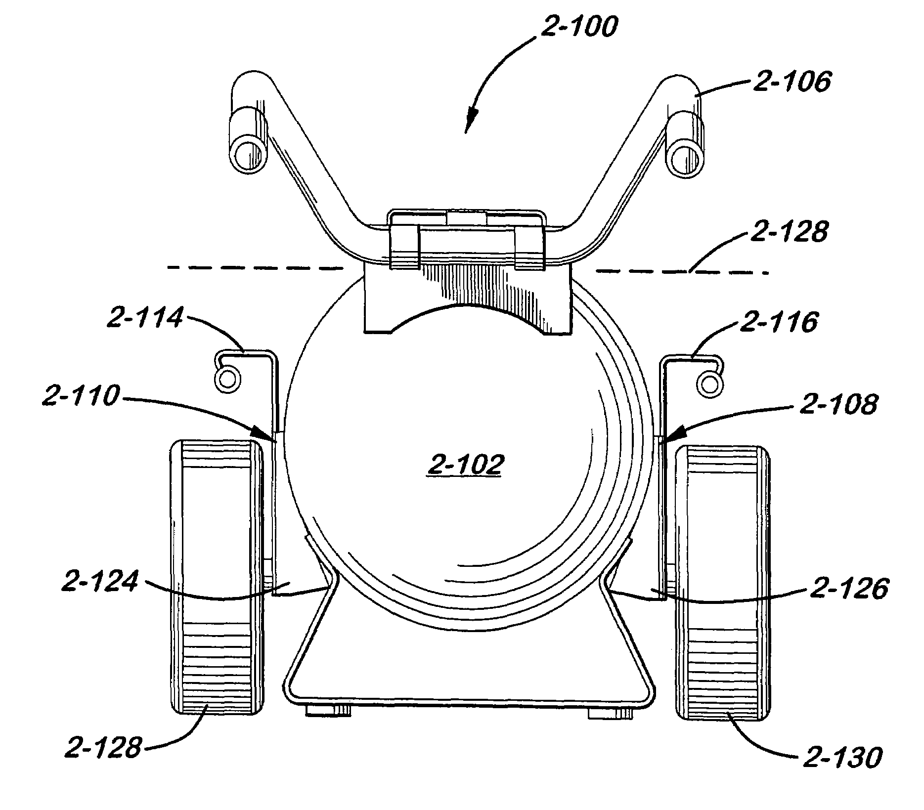
[0086]Reference will now be made in detail to the presently preferred embodiments of the invention, examples of which are illustrated in the accompanying drawings.

[0087]Referring generally to FIG. 2 through 14, exemplary embodiments of a first aspect of the present invention directed to a manifold assembly for an air compressor assembly that is capable of controlling and distributing compressed air from the air compressor assembly to one or more air powered tools are shown.

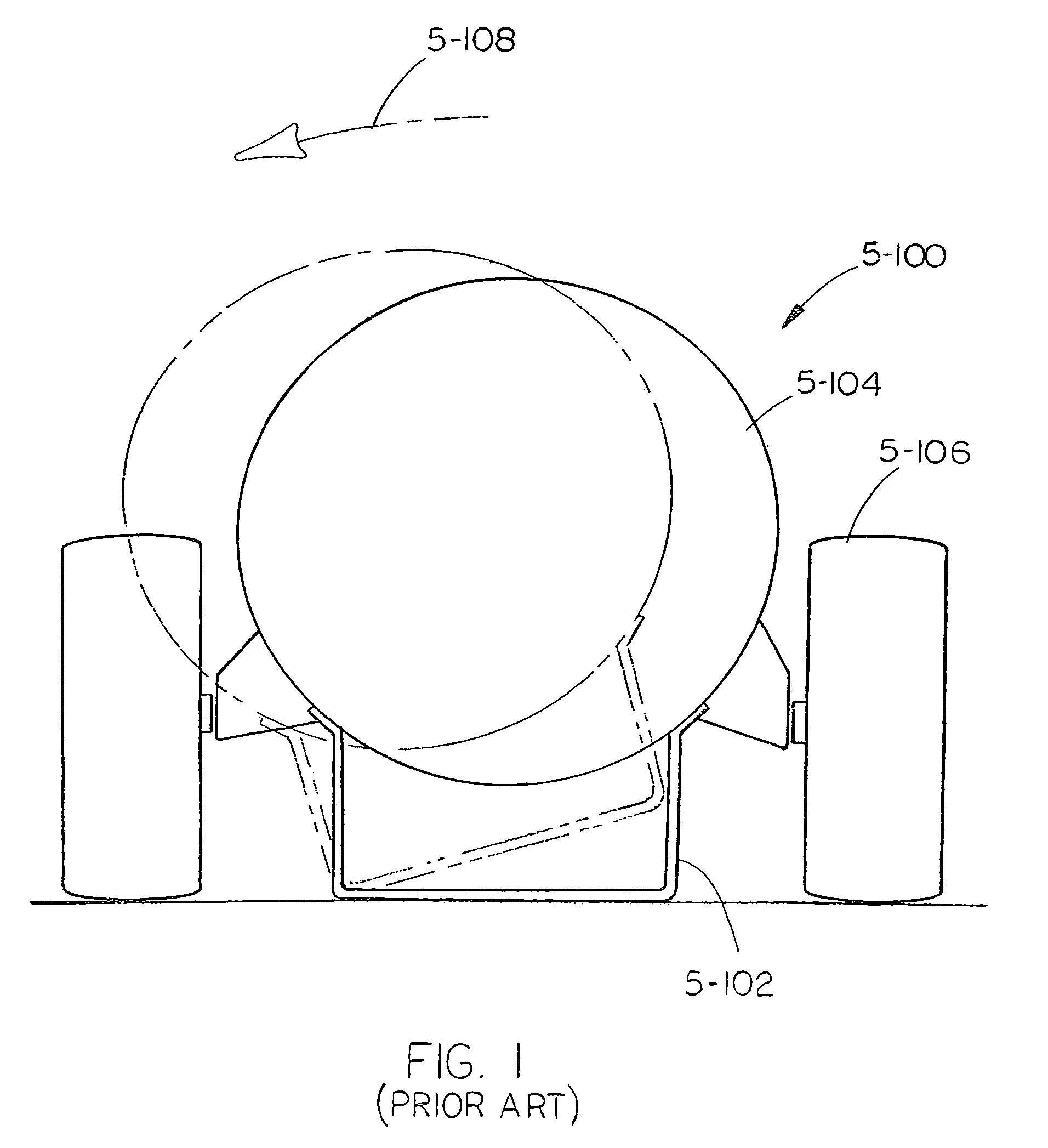
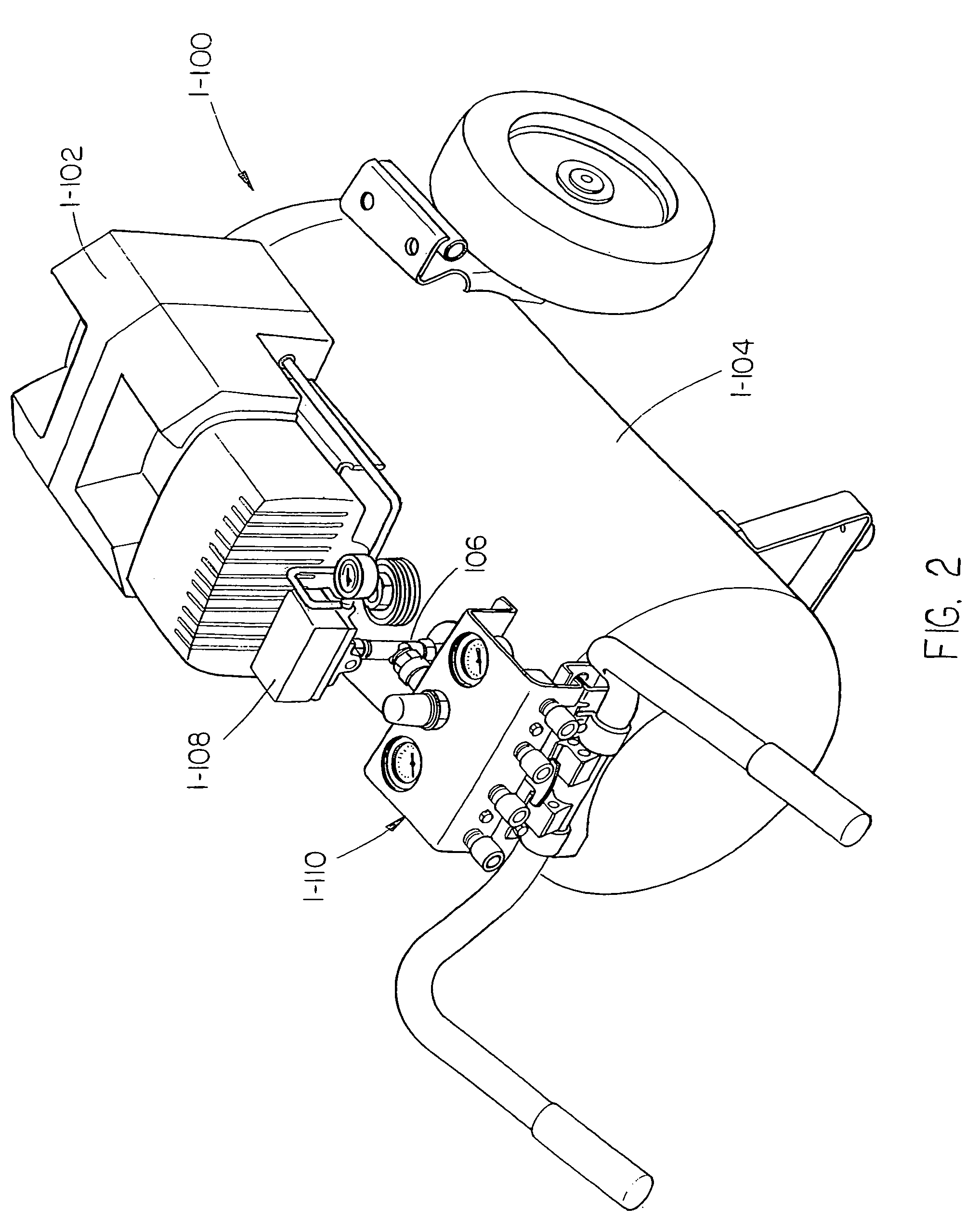
[0088]Referring generally to FIGS. 2 through 5, an air compressor assembly 1-100 in accordance with an exemplary embodiment of the present invention is described. As shown in FIGS. 2 and 3, the air compressor assembly 1-100 includes a compressor 1-102 mounted to a compressed air storage tank 1-104. The compressed air storage tank 1-104 provides a tank or receiver for storing air under pressure. A port (often referred to as a “spud”) is provided in the compressed air storage tank 1-104 to which a pressure manifold ...


PUM


Abstract

An air compressor assembly with one or more of the following features: a removable manifold assembly capable of being remotely located from the air compressor assembly for controlling and distributing compressed air from the air compressor assembly to one or more air powered tools, a lifting handle, a handle capable of assuming a plurality of positions, condensate removal devices, and a stable base and tie-down points.

Description

CROSS-REFERENCE TO RELATED DOCUMENTS[0001]The present application is a continuation of U.S. application Ser. No. 10 / 277,187, filed Oct. 21, 2002 now U.S. Pat. No. 6,742,995, which in turn is a continuation-in-part of U.S. application Ser. No. 09 / 802,149, filed Mar. 8, 2001, now U.S. Pat. No. 6,655,925, which claims the benefit under 35 U.S.C. § 119(e) of U.S. Provisional Application Ser. No. 60 / 187,744, filed Mar. 8, 2000; is a continuation-in-part of U.S. application Ser. No. 09 / 801,406, filed Mar. 8, 2001, now U.S. Pat. No. 6,532,990, which claims the benefit under 35 U.S.C. § 119(e) of U.S. Provisional Application Ser. No. 60 / 187,680, filed Mar. 8, 2000; is a continuation-in-part of U.S. application Ser. No. 09 / 801,408, filed Mar. 8, 2001, now U.S. Pat. No. 6,532,991, which claims the benefit under 35 U.S.C. § 119(e) of U.S. Provisional Application Ser. No. 60 / 187,723, filed Mar. 8, 2000; and is a continuation-in-part of U.S. application Ser. No. 09 / 802,139, filed Mar. 8, 2001, n...

Claims


Application Information

Patent Timeline
IPC IPC(8): F04B53/00A01G25/09B67D5/00B67D99/00F04B35/06F04B41/02F04B49/00
CPCF04B35/06F04B49/00F04B41/02Y10T137/5109Y10T137/6914Y10T137/7837Y10T137/86051
Inventor WOOD, MARK W.BURKHOLDER, ROBERT F.BARBOUR, CRANDALL B.DAVIS, MIKE L.MORGAN, FRED M.ROBENALT, DAVID W.SMITH, DAVE C.HARDIN, JOHN W.
Owner BLACK & DECKER INC
Why Eureka
Try Eureka