Reference sensor correction for implantable sensors

a technology of reference sensor and implantable sensor, which is applied in the field of drift correction of implantable sensing devices to achieve the effect of improving long-term measurement accuracy

Active Publication Date: 2008-08-19
DATA SCI INT
View PDF4 Cites 62 Cited by
  • Summary
  • Abstract
  • Description
  • Claims
  • Application Information

AI Technical Summary

Benefits of technology

[0007]To address this need, the present invention provides a variety of improvements to the design of chronically implantable pressure sensors. In exemplary embodiments, an implantable medical device (IMD) system and method is described for measuring a body parameter utilizing an implantable functional sensor and a fixed reference (or “dummy”) sensor, wherein the reference sensor compensates for drift of all components in the measurement system other than the functional sensor and the reference sensor. The reference sensor provides a basis for comparison to determine if and to what extent the electronic components, for example, have drifted over time, and thus provides a basis for correcting functional measurements and improving long term measurement accuracy. Illustrative embodiments of IMD systems and methods utilizing a reference sensor are described in more detail hereinafter.

Problems solved by technology

For example, in such a system, both the pressure sensor and the associated electronics may contribute significantly to drift.

Method used


Image

  • Reference sensor correction for implantable sensors
  • Reference sensor correction for implantable sensors
  • Reference sensor correction for implantable sensors

Examples


Embodiment Construction

[0013]The following detailed description should be read with reference to the drawings in which similar elements in different drawings are numbered the same. The drawings, which are not necessarily to scale, depict illustrative embodiments and are not intended to limit the scope of the invention.

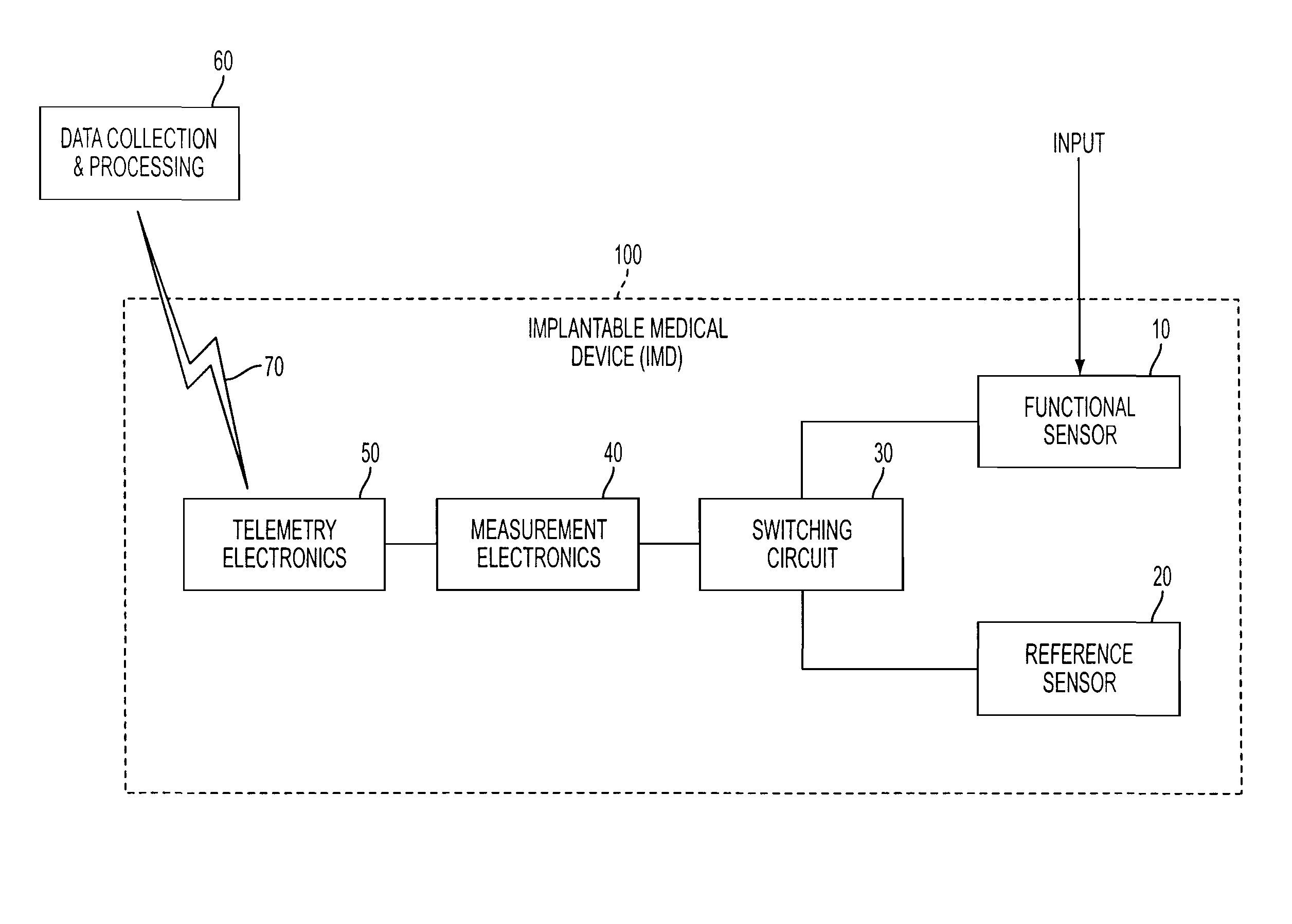
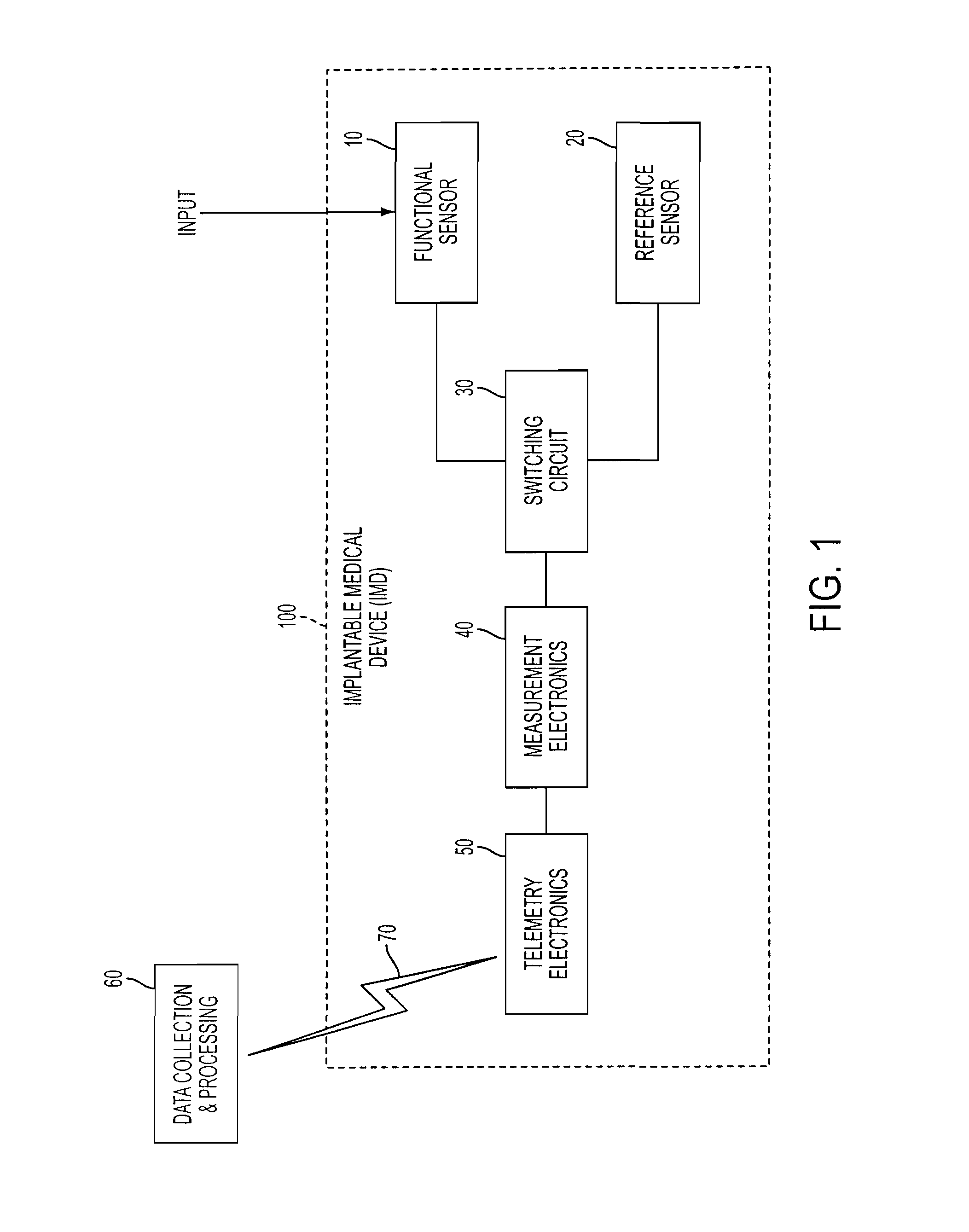
[0014]With reference to FIG. 1, an exemplary embodiment of an implantable medical device 100 is shown schematically. The IMD includes a functional sensor 10 which may comprise a pressure sensor for measuring a variable body parameter such as blood pressure, intracranial pressure, etc. The functional sensor 10 may be connected to a measurement electronics module 40 via switching circuit 30. The measurement electronics module 40 may comprise, for example, a signal processing circuit. The measurement electronics module 40, in addition to other electronic components other than the functional sensor 10, may be susceptible to drift over time, and therefore a reference sensor 20 may be used to dete...


PUM


Abstract

Implantable medical device systems and methods for measuring a body parameter utilizing an implantable functional pressure sensor and a fixed reference sensor, wherein the reference sensor compensates for drift of all other components in the measurement system other than the functional sensor. The reference sensor provides a basis for comparison to determine if and to what extent the electronic components, for example, have drifted over time, and thus provides a basis for correcting functional measurements and improving long term measurement accuracy.

Description

GOVERNMENT LICENSE RIGHTS[0001]Portions of the subject matter disclosed herein were developed under Grant No. 8R44EB00354 awarded by the U.S. Department of Health and Human Services, National Institutes of Health, and therefore, the U.S. Government may have rights to certain claimed inventions.CROSS-REFERENCE TO RELATED APPLICATIONS[0002]The present application is related to U.S. patent application Ser. No. 10 / 717,179, filed Nov. 17, 2003, entitled Implantable Pressure Sensors, the entire disclosure of which is incorporated herein by reference.FIELD OF THE INVENTION[0003]The present invention relates to drift correction of implantable sensing devices, such as implantable pressure sensors.BACKGROUND OF THE INVENTION[0004]An example of an implantable pressure sensing device is disclosed in U.S. Pat. No. 4,846,191 to Brockway et al. Such an implantable pressure sensing device utilizes a sensor assembly including a pressure sensor and a fluid-filled catheter. The fluid-filled catheter r...

Claims


Application Information

Patent Timeline
Patent Type & Authority Patents(United States)
IPC IPC(8): A61B5/00
CPCA61B5/0215A61B2560/0223
Inventor LICHTSCHEIDL, GREGG R.MILLS, PERRY A.
Owner DATA SCI INT
Why Eureka
Try Eureka