Method and circuit for driving liquid crystal display

a liquid crystal display and circuit technology, applied in the direction of instruments, static indicating devices, etc., can solve the problems of high power consumption, complex driving circuitry, and rare adoption of frame inversion methods, and achieve the effect of reducing power consumption and maximising the capacitance of storage capacitors

Active Publication Date: 2008-08-19
INNOLUX CORP
View PDF1 Cites 7 Cited by
  • Summary
  • Abstract
  • Description
  • Claims
  • Application Information

AI Technical Summary

Benefits of technology

[0014]According to another aspect of the present invention, a Vcom inversion driving method can be applied to a self-aligned process allowing further size reduction of a TFT. This method can also reduce the power consumption.
[0019]In one aspect of the present invention, a driving method for driving an LCD of the present invention uses two different AC signals to provide different reference voltages for a storage capacitor and a liquid crystal capacitor in a pixel respectively. In another aspect of the present invention, to maintain a voltage difference between the storage capacitor and the liquid crystal capacitor, the two different AC signals have to be synchronized and have same amplitude. In yet another aspect of the invention, the AC signal for the storage signal has an additional DC offset voltage more than that for the liquid crystal signal to maintain the maximum capacitance for the storage capacitor. Therefore, the present invention can use the self-aligned process to reduce the power consumption.

Problems solved by technology

Hence, the frame inversion method is rarely adopted.
The dot inversion method can provide a best image quality, but requires a higher power and a complex driving circuitry.
The aforementioned inversion driving method causes higher power consumption because the inversion has to be made each time after the data signal enters the pixel, which requires higher voltage amplitude and higher inversion frequency.
However, because a common electrode of the storage capacitor 330 and that of the liquid crystal capacitor 320 are coupled to the same voltage level, if the storage capacitor 330 is an asymmetric capacitor with polarity, the Vcom inversion driving method cannot be used.
The traditional optical alignment would not be able to meet the precision requirement.
Hence, the conventional Vcom inversion drive method cannot be used to reduce the power consumption.

Method used


Image

  • Method and circuit for driving liquid crystal display
  • Method and circuit for driving liquid crystal display
  • Method and circuit for driving liquid crystal display

Examples


Embodiment Construction

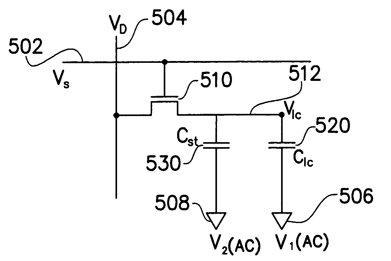
[0032]FIG. 5A is an equivalent pixel driving circuit for an active LCD in accordance with one embodiment of the present invention. A scan signal (VS) 502 is sent to a gate of the transistor 510 to turn the transistor 510 on / off. A data signal (VD) 504 is sent to a source of the transistor 510. When the transistor 510 is on, the data signal 504 will go through the transistor 510 to obtain an internal voltage (Vlc) 512. The internal voltage 512 then is stored in a storage capacitor (Cst) 530 and a liquid crystal capacitor (Clc) 520. One end of the storage capacitor 530 and one end of the liquid crystal capacitor 520 are coupled to a drain of the transistor 510. The other end of the storage capacitor 530 is coupled to a second AC signal (V2) 508. The other end of the liquid crystal capacitor 520 is coupled to a first AC signal (V1) 506.

[0033]FIG. 5B shows time sequences of the first and the second signals shown in FIG. 5A. In this embodiment, the second AC signal V2 has a DC offset vol...


PUM


Abstract

A method and circuit for driving LCD are provided. Because the conventional Vcom inversion drive method cannot be applied in a self-aligned process, the power consumption cannot be reduced when the size of the transistor decreases. The method and circuit provided uses two different AC signals to provide different reference voltages for the storage capacitor and the liquid crystal capacitor in a pixel respectively. Therefore, it can be applied to the self-aligned process to reduce the power consumption.

Description

CROSS-REFERENCE TO RELATED APPLICATION[0001]This application claims the priority benefit of Taiwan application serial no. 92125458, filed on Sep. 16, 2003.BACKGROUND OF THE INVENTION[0002]1. Field of the Invention[0003]This invention generally relates to a method and a circuit for driving a liquid crystal display, and more particularly to a Vcom inversion drive method and a circuit for driving a liquid crystal display.[0004]2. Description of Related Art[0005]There are several conventional drive methods for driving active liquid crystal displays (LCDs), such as a frame inversion method, a column inversion method, a row inversion method, and a dot inversion method. Anyone of the above methods can be chosen based on image quality, power consumption, and drive complexity. The frame inversion method is the simplest of the above methods, but provides a worst image quality compared to the other methods. Hence, the frame inversion method is rarely adopted. The dot inversion method can provi...

Claims


Application Information

Patent Timeline
Patent Type & Authority Patents(United States)
IPC IPC(8): G09G3/36
CPCG09G3/3648G09G2330/021G09G2300/0876
Inventor LIN, CHING-WEICHANG, SHIH-CHANGFANG, CHUN-HSIANG
Owner INNOLUX CORP
Why Eureka
Try Eureka