
Scanner and printer profiling system

a scanner and printer technology, applied in the field of color correction of computer peripheral devices, can solve the problems of properly calibrated scanners for photographic materials that misread printed materials, and achieve the effect of accurate color data collection and accurate printer icc profiles

Inactive Publication Date: 2008-08-19
X-RITE
View PDF22 Cites 16 Cited by
  • Summary
  • Abstract
  • Description
  • Claims
  • Application Information

AI Technical Summary

Benefits of technology

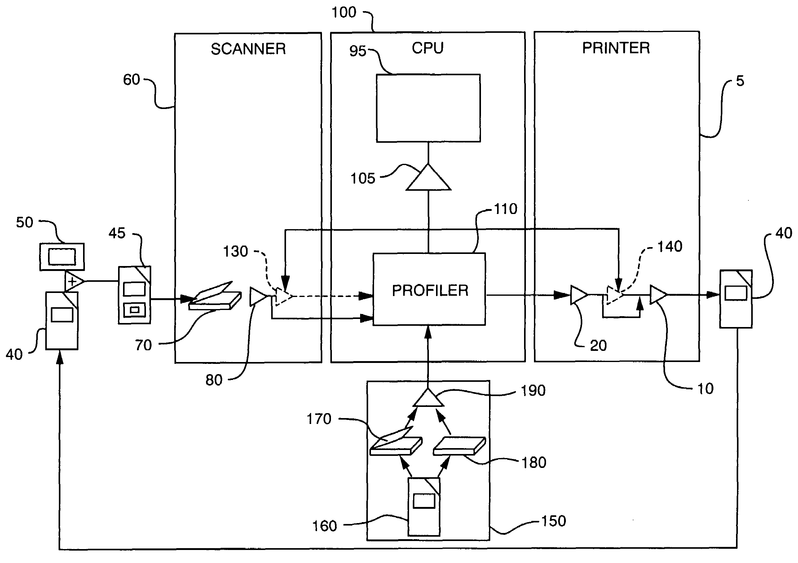
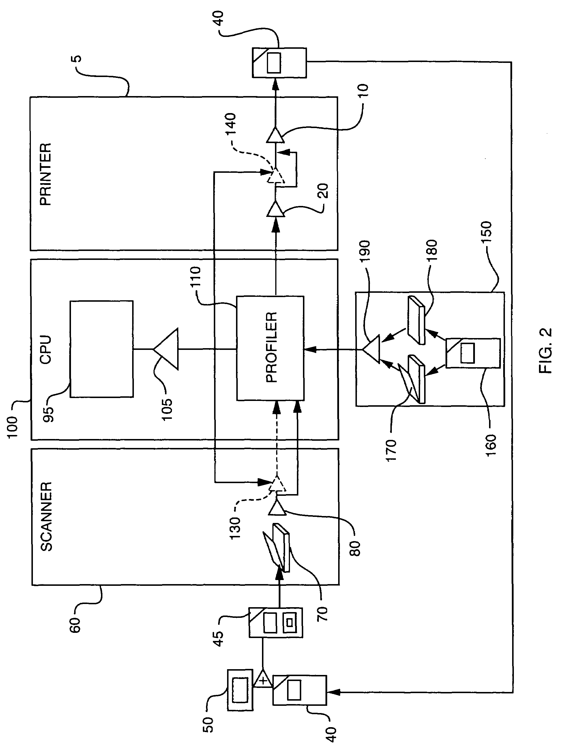
[0063]The present invention is to provide a color reproduction system that addresses the aforementioned problems. The present invention produces accurate printer ICC profiles from a scanner. The present system also produces a scanner ICC profile however the scanner profile is not a requirement of the invention. A scanner profile is created that can be used to process images intended for any output device. A printer profile is created that can be used to print images from any source. Using a scanner compensation table allows any scanner to function more closely to a spectrophotometer and ensures more accurate color data collection than can normally be obtained from a scanner.
[0064]Another feature of the invention is to scan the scanner calibration target at the same time as the printer calibration target, and use these targets to fully calibrate both the scanner and printer. Scanning both targets simultaneously significantly reduces scanner-setting errors, ensures the color data in both targets is measured under identical conditions, and decreases the profiling process.
[0065]Another aspect of the invention is the compensation color transform that improves the quality of the color reading produced by the scanner. The compensation transform compensates for the difference between how a scanner scans a photographic target and how it scans a printed target. Photographic and printed materials all have unique spectral properties that a scanner is sensitive to and can measure. The differences between photographic and printed materials are often large enough to cause a scanner that has been properly calibrated for photographic material to misread printed material. The algorithms of the present invention map the same RGB value from a scanner to different CIEL*a*b* values when the RGB values come from patches with different ink values.
[0069]Yet another feature is the use of a scanner compensation table that allows any scanner to function more closely to a spectrophotometer and ensures more accurate color data collection than can normally be obtained from a scanner.
[0070]Yet a further embodiment of the invention includes scanning both the reference target and the print target simultaneously thereby reducing scanner-setting errors and ensuring the color data in both targets is measured under identical conditions. Scanning simultaneously, these targets can be used to fully calibrate both the scanner and printer.

Problems solved by technology

The differences between photographic and printed materials are often large enough to cause a scanner that has been properly calibrated for photographic material to misread printed material.

Method used


Image

  • Scanner and printer profiling system
  • Scanner and printer profiling system
  • Scanner and printer profiling system

Examples


Embodiment Construction

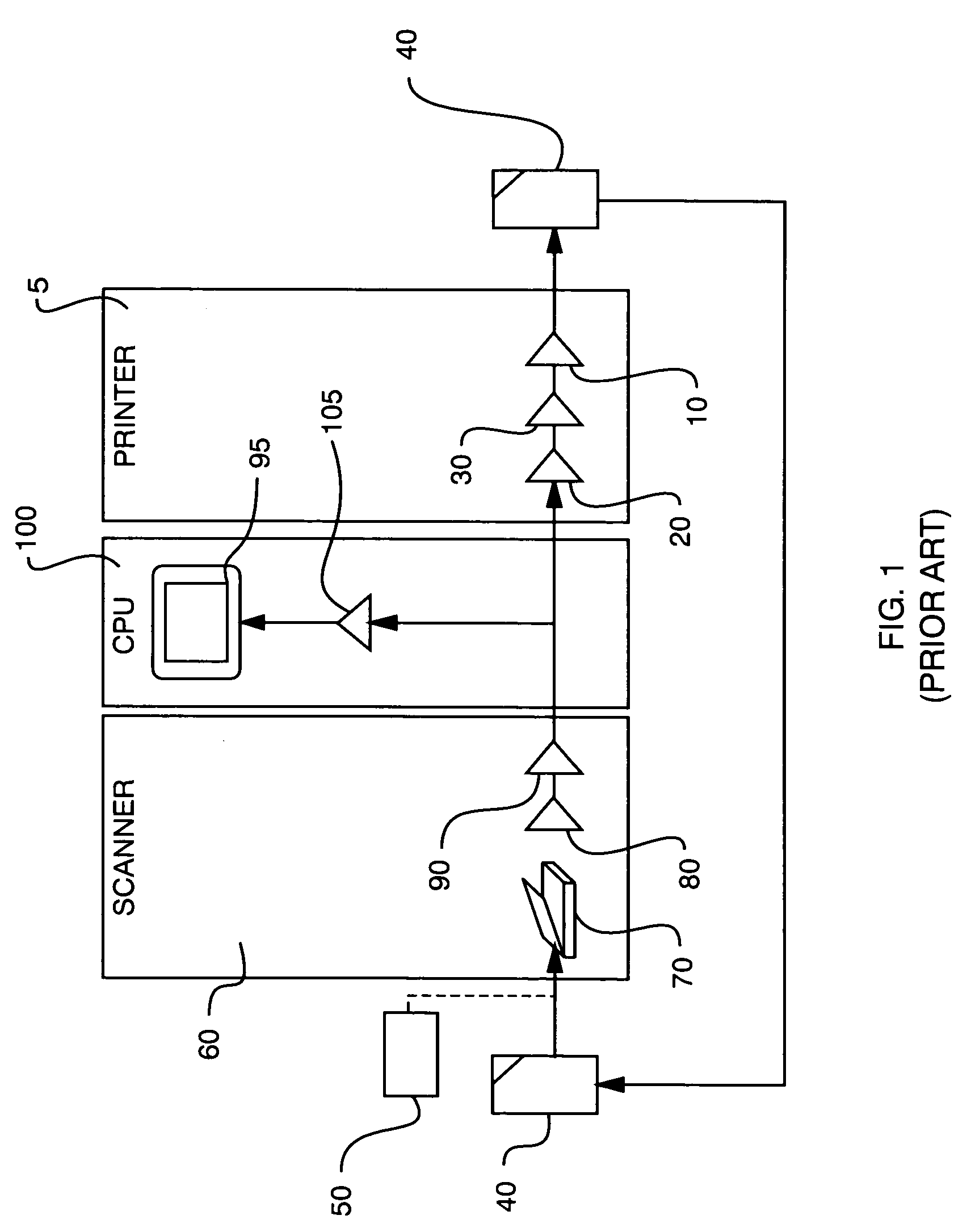
[0108]A prior art profiling system is illustrated in FIG. 1, having a printer section 5 containing a printer 10, an associated printer driver program 20 and a printer ICC profile 30. The printer driver 20 is the interface between the user and the printer section 5, and has the software commands to control the printer 10. The printer ICC profile 30 contains data and information that is used by the digital processing schemes to make the color reproductions. A scanner section 60 has a scanner device 70, a scanner driver 80, and a scanner ICC profile 90. The computer or CPU 100 is the processing and memory means for the system and is interconnected to the various components, which may include any number of image source devices such as a digital camera, internet access, DVD, and CD-ROM. A monitor 95 provides the visual interface to the user and a monitor ICC profile 105 provides the color correction for the display.

[0109]In a prior art operation, the CPU 100 sends a print instruction to ...


PUM


Abstract

An improved color correction system and more specifically, a color profiling system for a printer and scanner. Highly accurate device independent printer profiles are generated using a scanner and processing means. The process utilizes the simultaneous scanning of a reference target and a print target to produce a scanner profile. Uncompensated printer profile is developed using the scanner profile and compensation transforms convert the uncompensated printer profile into the printer profile.

Description

RELATED APPLICATIONS[0001]This application is a divisional of U.S. application Ser. No. 09 / 475,576, filed Jan. 5, 2000 and is herein incorporated in its entirety by reference.FIELD OF THE INVENTION[0002]The present invention relates most generally to color correction of computer peripheral devices and more particularly to a color profiling system for a printer and scanner.BACKGROUND OF THE INVENTION[0003]Color is defined as the perceptual result of light in the visible region of the spectrum. The human retina has three types of color photoreceptor cells for illumination therefore it is possible to define color using only three numerical components.[0004]The Commission Internationale de L'Éclairage (CIE) created a standardized system for representing color illuminations using three numerical components to represent the mathematical coordinates of color space. The colors produced by reflective systems are a function not only of the colorants but also of the ambient illumination that r...

Claims


Application Information

Patent Timeline
IPC IPC(8): G06F15/00H04N1/60
CPCH04N1/00068H04N1/00087H04N1/6033H04N1/00063H04N1/00015H04N1/00045H04N1/00047H04N1/00013
Inventor ADAM, GEORGE EVOGH, JR., JAMES W
Owner X-RITE
Learn More