
Inverter

a technology of inverter and inverter, which is applied in the direction of ac-dc conversion, electric variable regulation, electric power transfer ac network, etc., can solve the problems of low load operation efficiency of three-phase inverter and immediate full intrinsic consumption of inverter, and achieve low load operation high efficiency

Inactive Publication Date: 2008-08-19
KOSTAL IND ELEKTRIK
View PDF7 Cites 158 Cited by
  • Summary
  • Abstract
  • Description
  • Claims
  • Application Information

AI Technical Summary

Benefits of technology

[0008]Accordingly, an object of the present invention includes a multi-phase inverter having a high efficiency in low load operation.
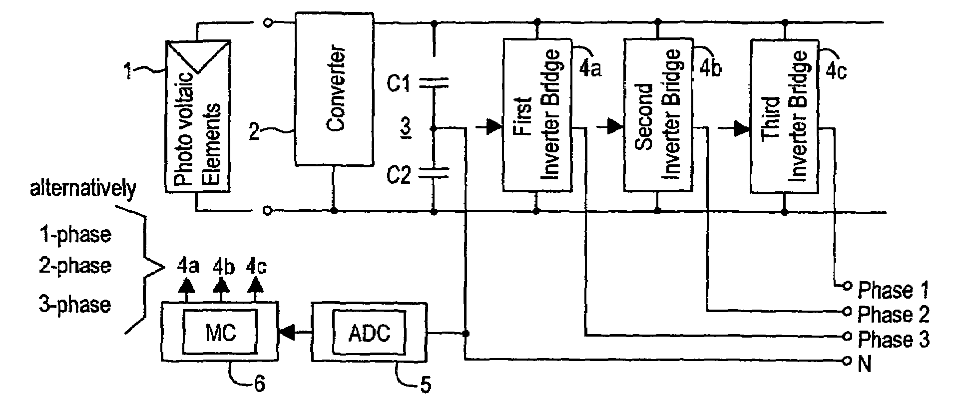
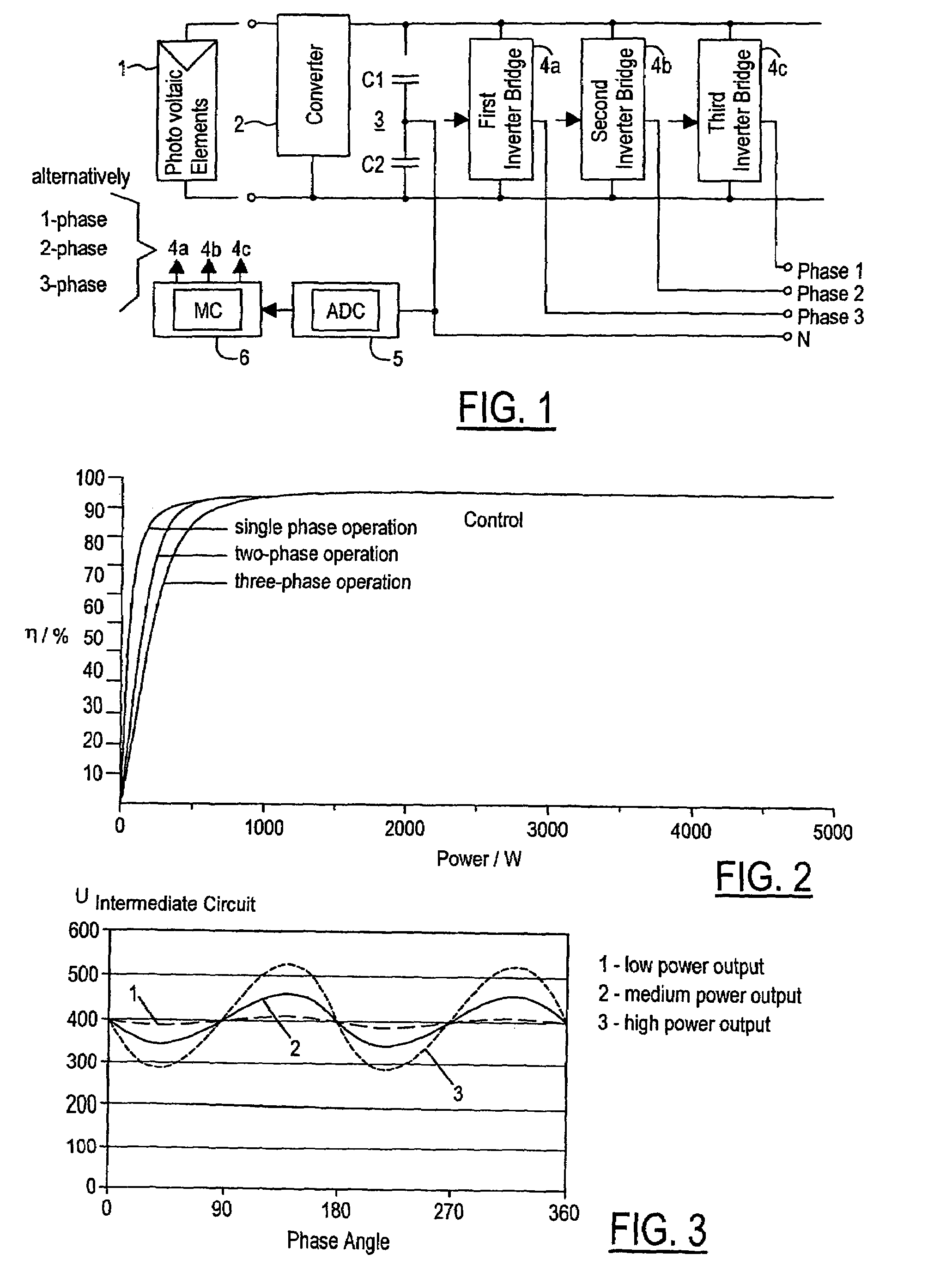
[0018]A goal of a multi-phase inverter in accordance with embodiments of the present invention is to have reduced intrinsic consumption especially during low load operation (i.e., the partial-load range). This goal is accomplished by connecting the inverter bridge branches one at a time as a function of the load operation of the inverter. For instance, with a three-phase inverter having three inverter bridge branches, the first inverter bridge branch (i.e., one phase) is connected under relatively low loads while the second and third inverter bridge branches being disconnected, then the second inverter bridge branch along with the first inverter bridge branch (i.e., two phase) are connected under relatively medium loads with the third inverter bridge branch being disconnected, and then the third inverter bridge branch along with the first and second inverter bridge branches (i.e., three phase) are connected under relatively high loads. Likewise, the first, second,. and third inverter bridge branches (i.e., three phase) are connected under relatively high loads, then only the first and second inverter bridge branches (i.e., two phase) are connected under relatively medium loads with the third inverter bridge branch being disconnected, and then only the first inverter bridge branch (i.e., one phase) is connected under relatively low loads with the second and third inverter bridge branches being disconnected.
[0022]Accordingly, a three-phase inverter in accordance with embodiments of the present invention combines advantages of a three-phase inverter in accordance with the background art with advantages of either a single-phase inverter or a two-phase inverter. Namely, a three-phase inverter in accordance with embodiments of the present invention provides the possibility of multi-phase feeding into a power network during high load operation with high efficiency during low load operation. Thus, the overall efficiency of a photovoltaic system can be increased as compared to a single-phase inverter in the lower partial-load range and compared to a three-phase inverter in accordance with the background art.

Problems solved by technology

As a result, a problem with the typical inverter is that the inverter immediately has full intrinsic consumption.
A problem is that this three-phase inverter has a lower efficiency in low load operation than a single-phase inverter or a two-phase inverter.

Method used


Image

  • Inverter
  • Inverter

Examples


Embodiment Construction

)

[0028]Referring now to FIG. 1, a block diagram of a three-phase inverter in accordance with an embodiment of the present invention is shown. The inverter includes an a direct voltage / direct voltage (DC / DC) converter 2, an intermediate circuit 3, and first, second, and third inverter bridge branches 4a, 4b, 4c.

[0029]The inverter feeds photovoltaic produced electrical energy from photovoltaic elements 1 into a three-phase power network. Photovoltaic elements 1 are connected to the input side of the inverter. Photovoltaic elements 1 provide a direct current (DC) voltage to DC / DC converter 2. DC / DC converter 2 adapts the input voltage to the voltage level required on the output side of the inverter.

[0030]Intermediate circuit 3 includes a capacitor arrangement downstream of DC / DC converter 2. The capacitor arrangement includes capacitors C1, C2. Capacitors C1, C2 are used to store or buffer energy. Inverter bridges 4a, 4b, 4c are downstream of the capacitor arrangement on the output si...


PUM


Abstract

An inverter includes an intermediate circuit, inverter bridge branches downstream of the intermediate circuit for outputting a power signal, and a controller operable for individually turning on and off the inverter bridge branches. The controller may individually turn on and off the inverter bridge branches as a function of an electrical quantity. The electrical quantity may be indicative of a voltage or a change in voltage occurring in the intermediate circuit during operation of the inverter. The electrical quantity may be indicative of the output power signal. The inverter bridge branches may include three inverter bridge branches.

Description

CROSS-REFERENCE TO RELATED APPLICATIONS[0001]This is a continuation of International Application PCT / EP2006 / 001736, published in German, with an international filing date of Feb. 24, 2006, which claims priority to DE 10 2005 008 809.0, filed Feb. 26, 2005, the disclosures of which are both hereby incorporated by reference.BACKGROUND OF THE INVENTION[0002]1. Field of the Invention[0003]The present invention relates to an electrical inverter having an intermediate circuit and a plurality of inverter bridge branches.[0004]2. Background Art[0005]An inverter has one, two, or three inverter bridge branches on its output side to correspondingly produce an output voltage having one, two, or three phases. A typical inverter switches on as an entire unit. As a result, a problem with the typical inverter is that the inverter immediately has full intrinsic consumption.[0006]DE 199 37 410 A1 describes an inverter having three inverter bridge branches on its output side to produce a three-phase c...

Claims


Application Information

Patent Timeline
Patent Type & Authority Patents(United States)
IPC IPC(8): H02M7/5387H02M5/45H02M7/537
CPCH02M7/42H02M1/10
Inventor ROTTGER, DIETERVOGEL, THOMAS
Owner KOSTAL IND ELEKTRIK
Learn More