
Method and system for control of capacity in a communication network

a communication network and capacity control technology, applied in the field of dynamic control of capacity, can solve the problems of reducing the cost of overall user capacity, and increasing the overall user capacity

Inactive Publication Date: 2008-08-19
GOOGLE TECHNOLOGY HOLDINGS LLC
View PDF18 Cites 7 Cited by
  • Summary
  • Abstract
  • Description
  • Claims
  • Application Information

AI Technical Summary

Benefits of technology

The present invention relates to wireless communication networks and devices, such as cell phones or radios, that can dynamically control capacity to improve performance. The invention provides a way to balance network performance and user capacity, making trade-offs between the two. By controlling capacity, the invention can improve throughput and user experience, while also reducing latency and improving reliability. The invention can be applied to communication systems providing voice and data services over cellular wide area networks, and can be implemented in communication devices with WLAN capabilities. The invention is useful for enhancing understanding and optimizing performance of wireless communication networks.

Problems solved by technology

This may result in higher throughput per user on a wireless data connection, but normally at the cost of reduced overall user capacity.
Conversely, a higher configured BLER can be set or targeted by the network operator and this may increase the overall user capacity, but ordinarily at the cost of lower throughput per user.
For example, TCP (transport control protocol) applications can suffer from a lower throughput when the BLER (block error rate) is high; TCP congestion procedures can be triggered due to the higher delay of UTRAN (universal terrestrial radio access network) RLC (radio link control) retransmissions on the air interface.

Method used


Image

  • Method and system for control of capacity in a communication network
  • Method and system for control of capacity in a communication network
  • Method and system for control of capacity in a communication network

Examples


example 1

Target BLER Value Determination

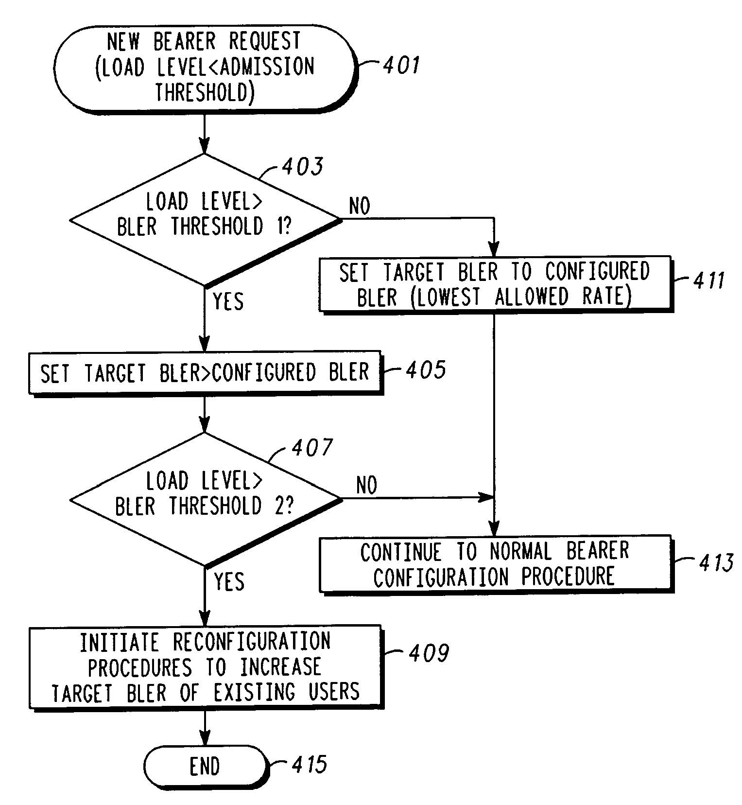
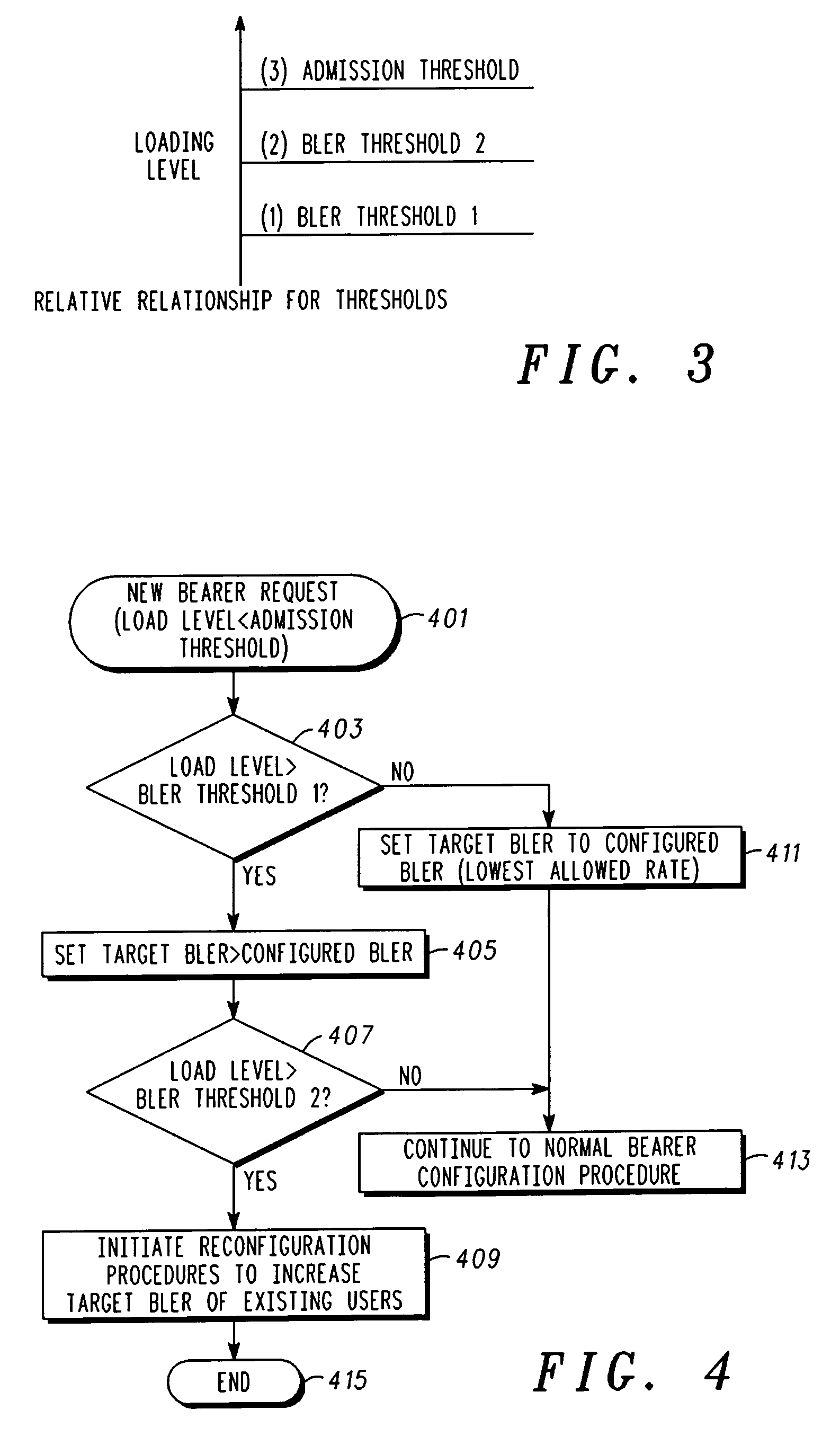
[0050]The following section provides an example utilizing BLER for illustration purposes, wherein new target BLER values are determined based on a load level calculation. (Note: “*” throughout this example indicates a value that can be preconfigured in a database storing information utilized by the calculation.)

[0051]Conventional Parameter Derived from Internal System Calculation:

[0052]Load Level=Calculated measure of cell load used for admission control purposes.

[0053]Conventional Operator Configurable Parameters:

[0054]Admission Threshold*=Configurable loading level threshold used for decision on admitting new users.

[0055]Configured BLER*=BLER Target from database. Acts as lowest BLER target to be used for this service type.

[0056]Exemplary Operator Configurable Parameters in Accordance with One or More Embodiments:

[0057]BLER_Thresh—1*=Configurable Loading Level threshold used to determine BLER target for current pending user.

[0058]BLER_Thresh—2*=Confi...


PUM


Abstract

A controller (103a, 103b) provides dynamic capacity, for use in connection with a communication network (101). A processor of the controller (103a, 103b) that can be utilized in the communication network can be configured to facilitate determining whether a current load level is below a predetermined low usage, and responsive thereto, adjusts a bearer configuration to allow higher throughput per user. Further, the processor (103a, 103b) can be configured to facilitate determining whether the current load level exceeds a predetermined high usage, and responsive thereto, adjusting the bearer configuration to allow lower throughput per user.

Description

FIELD OF THE INVENTION[0001]The present invention relates in general to wireless communication units and wireless networks, and more specifically to dynamically controlling capacity.BACKGROUND OF THE INVENTION[0002]In traditional communication networks, operators may be provided with an ability to make network configuration decisions to affect quality of service (QoS). Changes to the network configuration that affect QoS are static. Typically, the network configuration achieved thereby trades off capacity of the communication network for increased performance in connection with specific service types. For example, a relatively lower block error rate (BLER) can be set, configured, or targeted in the network configuration. This may result in higher throughput per user on a wireless data connection, but normally at the cost of reduced overall user capacity. Conversely, a higher configured BLER can be set or targeted by the network operator and this may increase the overall user capacit...

Claims


Application Information

Patent Timeline
Patent Type & Authority Patents(United States)
IPC IPC(8): G08C15/00H04J3/16H04J3/18H04L12/56H04Q7/20H04W28/18H04W28/20
CPCH04W28/18H04W28/20
Inventor GILLILAND, DENNIS W.WITHERELL, MICHAEL S.
Owner GOOGLE TECHNOLOGY HOLDINGS LLC
Learn More