Al technical title is built by PatSnap Al team. It summarizes the technical point description of the patent document.
a x-ray reflector and curved technology, applied in the field of x-ray optics, can solve problems such as bend moments in the assembly, and achieve the effect of low cos
Active Publication Date: 2008-08-19
BRUKER TECH LTD
View PDF13 Cites 27 Cited by
Summary
Abstract
Description
Claims
Application Information
AI Technical Summary
This helps you quickly interpret patents by identifying the three key elements:
Problems solved by technology
Method used
Benefits of technology
[0006]Embodiments of the present invention provide novel methods for producing optics based on curved crystals. These methods do not require the crystal to be pressed into a mold or bent using an external tool or die. Rather, the crystal is bent to the desired radius (or radii) of curvature by the stresses in a thin film layer deposited on the crystal. The curvature is determined by appropriate selection of the parameters of the deposition process and the geometry and dimensions of the thin film. This approach can be used to produce curved X-ray reflectors (including doubly-curved reflectors) simply and at low cost. The techniques disclosed hereinbelow are applicable to both single-crystal and polycrystalline materials, as well as to amorphous materials.
Problems solved by technology
These stresses cause tensile or compressive internal forces in the substrate / thin film assembly, which may cause bending moments in the assembly.
Method used
Image
Click on the blue label to locate the original text in one second.
Reading with bidirectional positioning of images and text.
Examples
Embodiment Construction
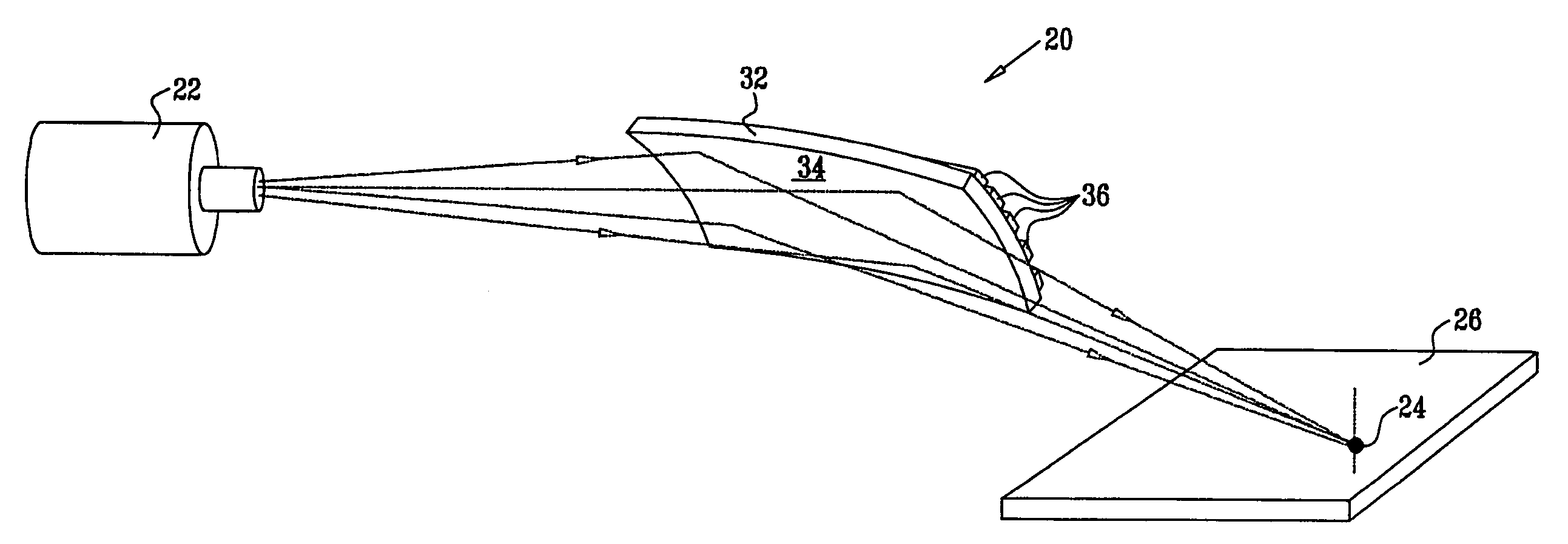
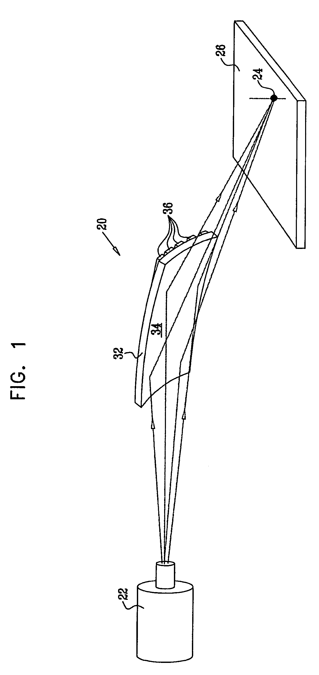
[0026]FIG. 1 is a schematic, pictorial illustration showing an X-ray reflector 20 used in an X-ray spectrometer, in accordance with an embodiment of the present invention. An X-ray source 22 emits a beam of X-rays, which are incident on reflector 20. The reflector is doubly-curved, and may have different radii of curvature about the X- and Y-axes. (In this example, the X-axis is taken to be the axis that is approximately parallel to the X-ray beam axis, while the Y-axis is transverse to the beam; but these axis designations are arbitrary and are chosen here solely for the sake of convenience.) The curvature and position of reflector 20 are chosen so that the reflector focuses the X-ray beam to a spot 24 on the surface of a sample 26. Alternatively, the reflector may be configured to produce a line focus on the sample. X-rays scattered from sample 26 are received by a detector (not shown), and the spectrum of the scattered X-rays is analyzed to determine properties of the sample, usi...
PUM
Abstract
A method for producing X-ray optics includes providing a wafer of crystalline material having front and rear surfaces and a lattice spacing suitable for reflecting incident X-rays of a given wavelength. A thin film is deposited on the front surface of the wafer so as to generate compressive forces in the thin film sufficient to impart a concave curvature to the rear surface of the wafer with at least one radius of curvature selected for focusing the incident X-rays.
Description
CROSS-REFERENCE TO RELATED APPLICATION[0001]This application claims the benefit of U.S. Provisional Patent Application 60 / 702,783, filed Jul. 26, 2005, which is incorporated herein by reference.FIELD OF THE INVENTION[0002]The present invention relates generally to X-ray optics, and specifically to methods for producing curved X-ray reflectors and devices made by such methods.BACKGROUND OF THE INVENTION[0003]Doubly-curved crystals are commonly used for focusing monochromatic radiation beams, particularly in the X-ray range, and for wavelength dispersion in X-ray spectrometers. To produce such devices, the crystal curvature must be carefully controlled to give the desired focusing properties. Exemplary methods for forming doubly-curved crystals of this sort are described in U.S. Pat. Nos. 4,807,268, 4,780,899, 4,949,367, 6,236,710 and 6,498,830, whose disclosures are incorporated herein by reference.[0004]When a thin film is deposited on a substrate, compressive or tensile stresses ma...
Claims
Application Information
Patent Timeline
Application Date:The date an application was filed.
Publication Date:The date a patent or application was officially published.
First Publication Date:The earliest publication date of a patent with the same application number.
Issue Date:Publication date of the patent grant document.
PCT Entry Date:The Entry date of PCT National Phase.
Estimated Expiry Date:The statutory expiry date of a patent right according to the Patent Law, and it is the longest term of protection that the patent right can achieve without the termination of the patent right due to other reasons(Term extension factor has been taken into account ).
Invalid Date:Actual expiry date is based on effective date or publication date of legal transaction data of invalid patent.