Image forming apparatus having charging unit with separate intake and exhaust ducts

a technology of image forming apparatus and exhaust duct, which is applied in the direction of electrographic process apparatus, instruments, optics, etc., can solve the problems of adversely affecting the surface of the photosensitive drum, developer spatter, image deterioration, etc., and achieve excellent efficiency and excellent efficiency , the effect of exhausting ozone with excellent efficiency

Active Publication Date: 2008-08-19
SHARP KK
View PDF11 Cites 5 Cited by
  • Summary
  • Abstract
  • Description
  • Claims
  • Application Information

AI Technical Summary

Benefits of technology

[0008]The present invention has been devised in consideration of these issues, and it is an object thereof to provide an image forming apparatus of a mode in which the surface of the photosensitive drum is charged by a charging unit such as a corona charging unit, structured such that the ozone produced within the charging unit can be reliably and efficiently removed.

Problems solved by technology

In this regard, ozone is produced inside the charging unit when using a corona charging unit as the charging unit, which presents a problem of image deterioration when the produced ozone becomes residual and adversely affects the surface of the photosensitive drum.
Furthermore, there is a problem that developer spatters during the development process and the inside of the apparatus becomes soiled by the spattered developer.
However, with conventional ventilation systems, air in the vicinity of the fixing device is also drawn so that the heat produced by the fixing device exerts an adverse influence on the image formation process.
For example, toner blocking, thermal deformation of the apparatus housing and other problems occur.
To avoid this influence, it has been necessary to install the fixing device and the portion for image formation processing apart from each other at a fixed distance, which presents an obstacle to miniaturization of the apparatus.
Furthermore, when carrying out ventilation for the entire apparatus including the vicinity of the fixing device, it has been necessary to use a large capacity exhaust fan and a dedicated duct, which also presents an obstacle to miniaturization.
Further still, with centralized ventilation systems, the ventilation within the charging units installed in the portion for image formation processing is incomplete, which makes it impossible to avoid image deterioration and reduced life of the image formation process due to such factors as ozone damage to the photosensitive drums and nitrogen oxides adhering to the grid of the charging units.

Method used


Image

  • Image forming apparatus having charging unit with separate intake and exhaust ducts
  • Image forming apparatus having charging unit with separate intake and exhaust ducts
  • Image forming apparatus having charging unit with separate intake and exhaust ducts

Examples


working example

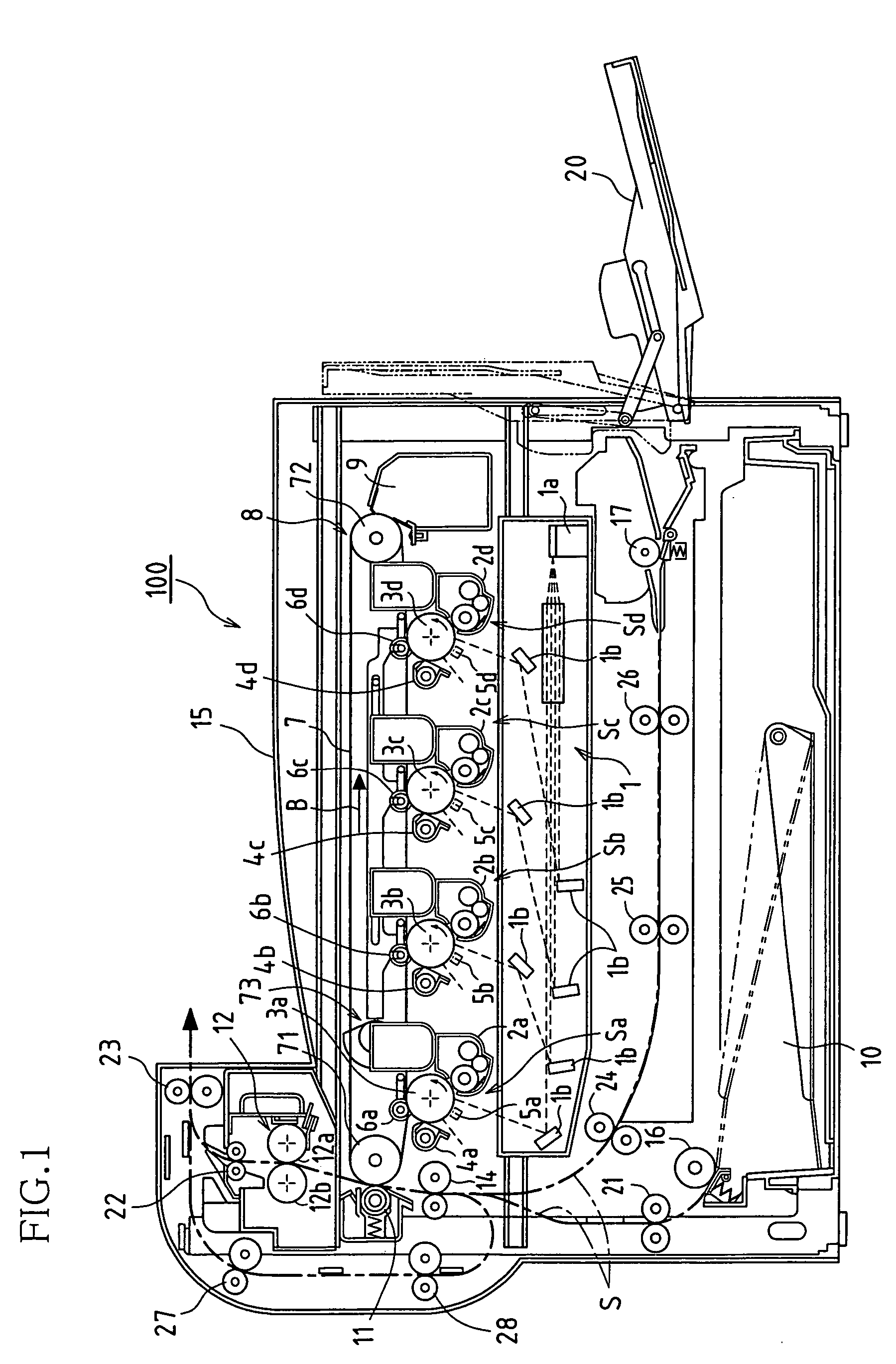
[0055]Next, characteristic aspects (working examples) of the present invention will be described with reference to FIGS. 2 to 8.

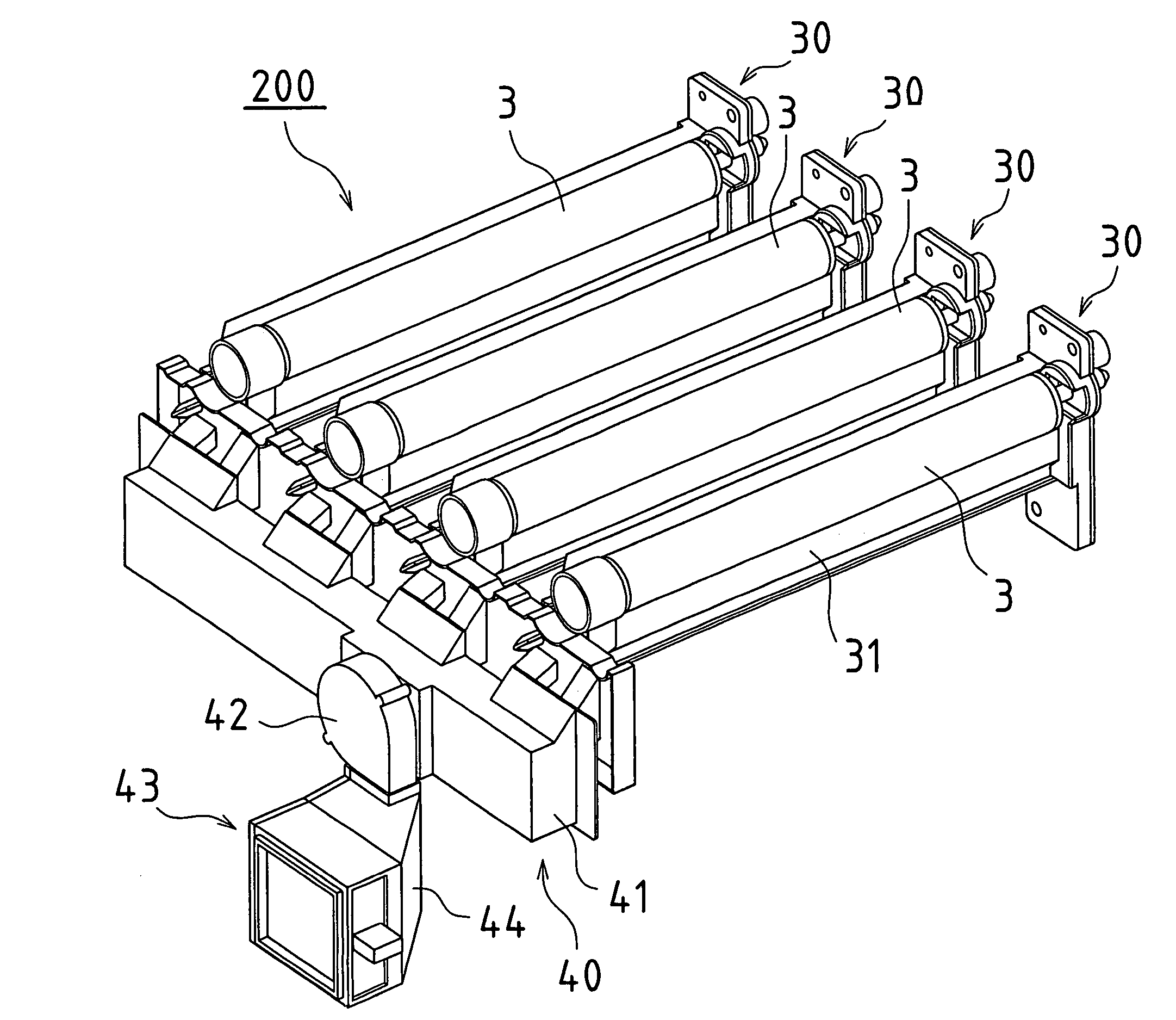
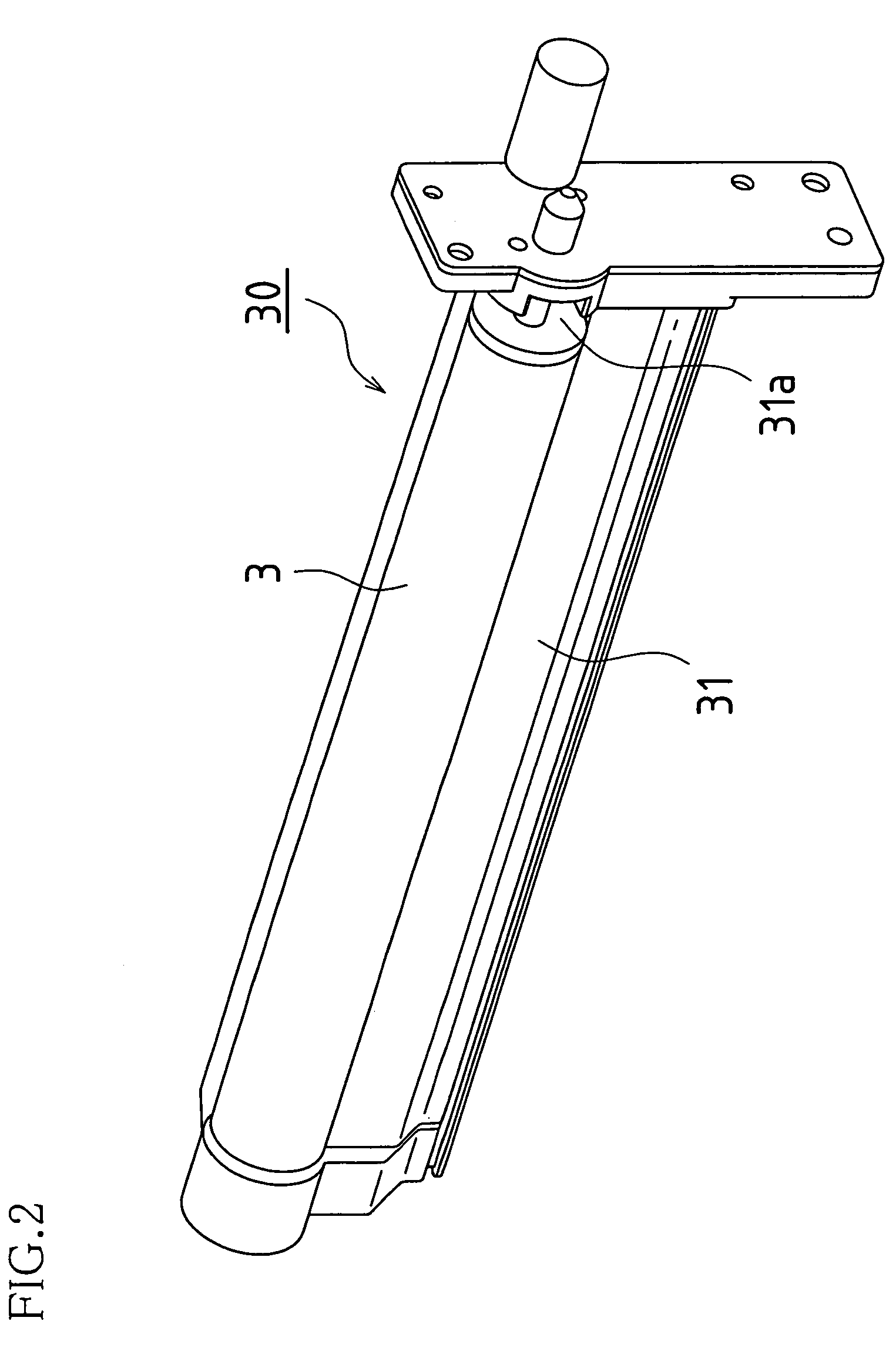
[0056]First, in this example, the four photosensitive drums 3a to 3d (hereinafter, each photosensitive drum is referred to as “photosensitive drum 3”) and the charging units 5a to 5d (hereinafter, each charging unit is referred to as “charging unit 5”) that correspond to each color of the image forming apparatus 100 are integrally configured in a respective drum unit 30. External views of the drum unit 30 are shown in FIGS. 2 and 3. Furthermore, FIG. 4 shows an external view of a ventilation unit 200 that integrates the four drum units 30 and incorporates an exhaust mechanism 40 that will be described later.

[0057]As shown in FIGS. 2, 3, and 5, an air introducing opening 31a and an air ejection opening 31b are provided in a unit case 31 of the drum unit 30.

[0058]The charging unit 5 is accommodated inside the unit case 31. The charging unit 5 is a corona char...


PUM


Abstract

In an image forming apparatus that uses a charging unit to charge a photosensitive drum, forms an electrostatic latent image by carrying out image exposure according to image information, and transfers to a paper the electrostatic latent image by developing the electrostatic latent image into a visible image using a developer so that the image information is presented, an exhaust duct 33 for exhausting air that contains ozone produced within a drum unit 30, which includes a photosensitive drum 3 and a charging unit 5, and a duct 32 for taking in air, which draws in fresh air, are provided within the drum unit 30 so that ventilation of the drum unit 30 can be carried out with excellent efficiency.

Description

CROSS REFERENCE TO RELATED APPLICATIONS[0001]This application claims priority under 35 U.S.C. § 119(a) on Patent Application No. 2004-199646 filed in Japan on Jul. 6, 2004, the entire contents of which are hereby incorporated by reference.BACKGROUND OF THE INVENTION[0002]The present invention relates to electrophotographic image forming apparatuses such as copying machines, laser printers, and facsimile machines, and more specifically relates to image forming apparatuses of a mode in which a surface of a photosensitive drum (electrostatic latent bearing member) is charged by a charging unit such as a corona charging unit.[0003]As electrophotographic image forming apparatuses such as copying machines, there are monochrome image forming apparatuses that form black and white images, and color image forming apparatuses that form color images. As color image forming apparatuses there are image forming apparatuses of a multiple rotation mode in which toner images of each color component a...

Claims


Application Information

Patent Timeline
Patent Type & Authority Patents(United States)
IPC IPC(8): G03G21/20
CPCG03G15/0258G03G2215/026
Inventor HORI, TAKASHINAKANO, KUNIAKIFUJII, TOMOHIKOIWAKURA, YOSHIE
Owner SHARP KK
Why Eureka
Try Eureka