Purge device, purge stocker, and cleaning method

a technology of purging device and purging stock, which is applied in the direction of storage device, cleaning process and apparatus, chemistry apparatus and processes, etc., can solve the problems of blowing the purging gas as the gas, and achieve the effect of high purity, efficient removal of particles, and simplified device configuration

Active Publication Date: 2020-04-07
MURATA MASCH LTD
View PDF3 Cites 0 Cited by
  • Summary
  • Abstract
  • Description
  • Claims
  • Application Information

AI Technical Summary

Benefits of technology

[0010]Furthermore, a purge device according to a preferred embodiment of the present invention in which the nozzle is a purge nozzle that is connected to a gas introduction port provided on the bottom surface of the container and that supplies a purge gas to the inside of the container through the gas introduction port, and blows the purge gas serving as the gas is able to simplify the device configuration because the purge nozzle serves also as a nozzle that performs cleaning. Even when an atmosphere gas is mixed at a distal end of the purge nozzle, the gas is blown out before purging, and hence purging is able to be performed with a purge gas having high purity. The purge device in which the purge controller starts the blowing of the purge gas through the purge nozzle based on information on conveyance of the container to a purge position is able to allow accurate grasping of a positional relation between the container and the purge nozzle based on the conveyance information, and is thus able to remove particles efficiently and reliably. The purge device in which the purge controller starts the blowing of the purge gas through the purge nozzle after conveyance of the container is started and before the gas introduction port and the purge nozzle are connected to each other is able to reduce waste of the purge gas as compared with a purge device that starts the blowing of the purge gas before the conveyance of the container is started. The purge device in which the purge controller starts the blowing of the purge gas through the purge nozzle in the state in which the bottom surface of the container and the purge nozzle face each other is able to reduce waste of the purge gas as compared with a purge device that blows the purge gas before the bottom surface of the container and the purge nozzle face each other. The purge device in which the purge controller starts the blowing of the purge gas through the purge nozzle in accordance with an operation of a transfer device that lowers the container from above the purge nozzle is able to remove particles efficiently and reliably because a gap between the container and the purge nozzle is reduced. The purge device in which the purge controller continues the blowing of the purge gas through the purge nozzle even after the gas introduction port in the container and the nozzle are connected to each other so that the purge gas is supplied to the inside of the container is able to quickly shift from the state of cleaning to the state of purging. The purge device in which the purge controller changes a flow rate of the purge gas before and after the gas introduction port in the container and the purge nozzle are connected to each other is able to use, for example, a flow rate suited for cleaning and a flow rate suited for purging as appropriate.

Problems solved by technology

Furthermore, the nozzle may be a purge nozzle that is connected to a gas introduction port provided on the bottom surface of the container and that supplies a purge gas to inside of the container through the gas introduction port, and may blow the purge gas serving as the gas.

Method used


Image

  • Purge device, purge stocker, and cleaning method
  • Purge device, purge stocker, and cleaning method
  • Purge device, purge stocker, and cleaning method

Examples


Embodiment Construction

[0019]Preferred embodiments are described below with reference to the drawings. In each of the figures referred to below, an XYZ coordinate system is used to describe the directions in the figure. In the XYZ coordinate system, the vertical direction is a Z direction, and the horizontal directions are an X direction and a Y direction.

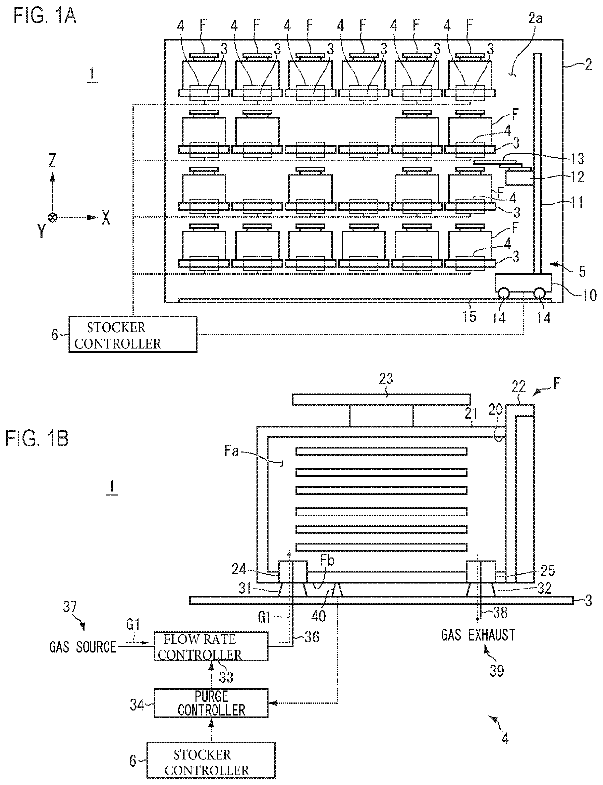
[0020]FIG. 1A is a diagram illustrating an example of a purge stocker 1 according to the present preferred embodiment. FIG. 1B is a diagram illustrating an example of a container F and a purge device 4. The purge stocker 1 is, for example, an automatic warehouse that stores therein containers F that are structured to contain articles such as wafers and reticles used to manufacture semiconductor elements. Examples of the containers F include FOUP, SMIF Pod, and reticle Pod. Reticles may be used for a liquid immersion exposure device or may be used for EUV.

[0021]As illustrated in FIG. 1A, the purge stocker 1 includes a casing 2, a plurality of storage shel...


PUM


Abstract

A purge device is capable of removing particles adhering to a gas introduction port in a container or on surrounding areas of a purge nozzle. The purge device includes a nozzle that is able to blow a gas, and a purge controller that controls the nozzle to blow the gas therethrough in a state in which a bottom surface of a container to be purged faces the nozzle.

Description

BACKGROUND OF THE INVENTION1. Field of the Invention[0001]The present invention relates to a purge device, a purge stocker, and a cleaning method.2. Description of the Related Art[0002]A purge stocker stores therein containers that are able to contain various kinds of articles such as wafers and reticles. Examples of the containers include FOUP, SMIF Pod, and reticle Pod. For storage of the containers, the purge stocker fills a purge gas such as clean dry air or nitrogen gas into the container by a purge device to suppress contamination and oxidation of contained matters. The purge device includes a purge port on which a container is placed and a purge nozzle connected to a gas introduction port in the container. The purge device supplies the purge gas to the inside of the container through the purge nozzle. When the container and the purge device are connected to each other, particles, resulting from contact between the gas introduction port and the purge nozzle, may adhere to the ...

Claims


Application Information

Patent Timeline
Patent Type & Authority Patents(United States)
IPC IPC(8): B08B5/02H01L21/677B65G1/00H01L21/673B08B9/08
CPCB08B9/0826B08B5/02H01L21/67389H01L21/67393B65G1/00H01L21/673H01L21/67733H01L21/67769B65G1/02B65G2201/0297H01L21/02041H01L21/67017
Inventor TSUBAKI, TATSUOMURATA, MASANAO
Owner MURATA MASCH LTD
Why Eureka
Try Eureka