Inkjet recording apparatus and cleaning method

a recording apparatus and cleaning technology, applied in printing and other directions, can solve the problems of ink being left on the intermediate transfer body rather than being transferred, affecting image quality, and foreign matter accumulating on the blade, and achieve the effect of increasing costs

Inactive Publication Date: 2011-04-19
FUJIFILM CORP
View PDF7 Cites 0 Cited by
  • Summary
  • Abstract
  • Description
  • Claims
  • Application Information

AI Technical Summary

Benefits of technology

[0010]The present invention has been contrived in view of these circumstances, an object thereof being to provide an inkjet recording apparatus and a cleaning method whereby ink and foreign matter remaining on an intermediate transfer body can be removed efficiently and reliably, without increasing costs due to consumables or the like.
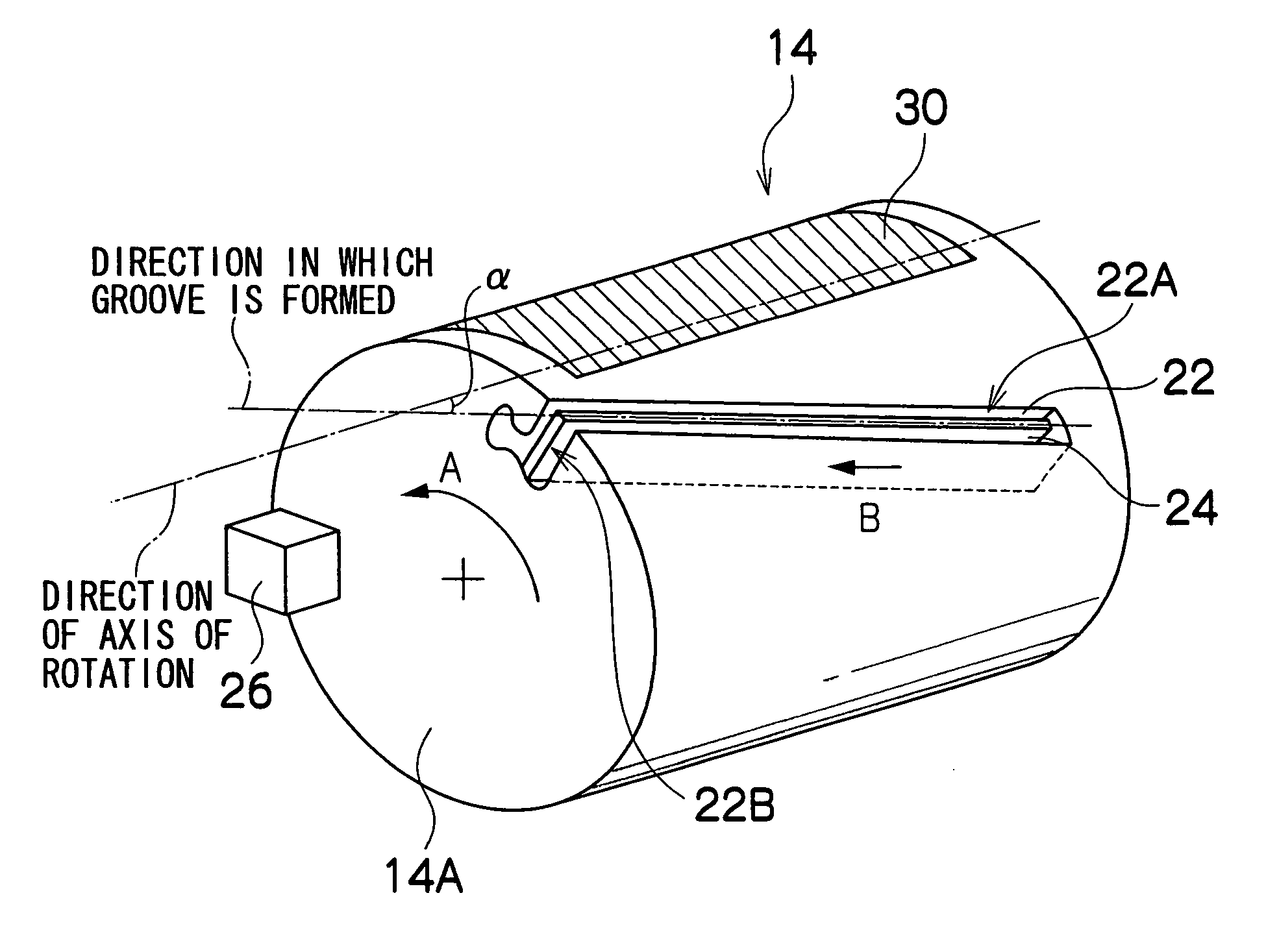
[0017]According to this aspect of the invention, since the ink inside the first groove is retained in the undercut section during movement of the intermediate transfer body, then leakage from the first groove is prevented. In this aspect of the invention, particularly notable effects are exerted in a mode where a drum-shaped intermediate transfer body is used and the first groove is rotated.
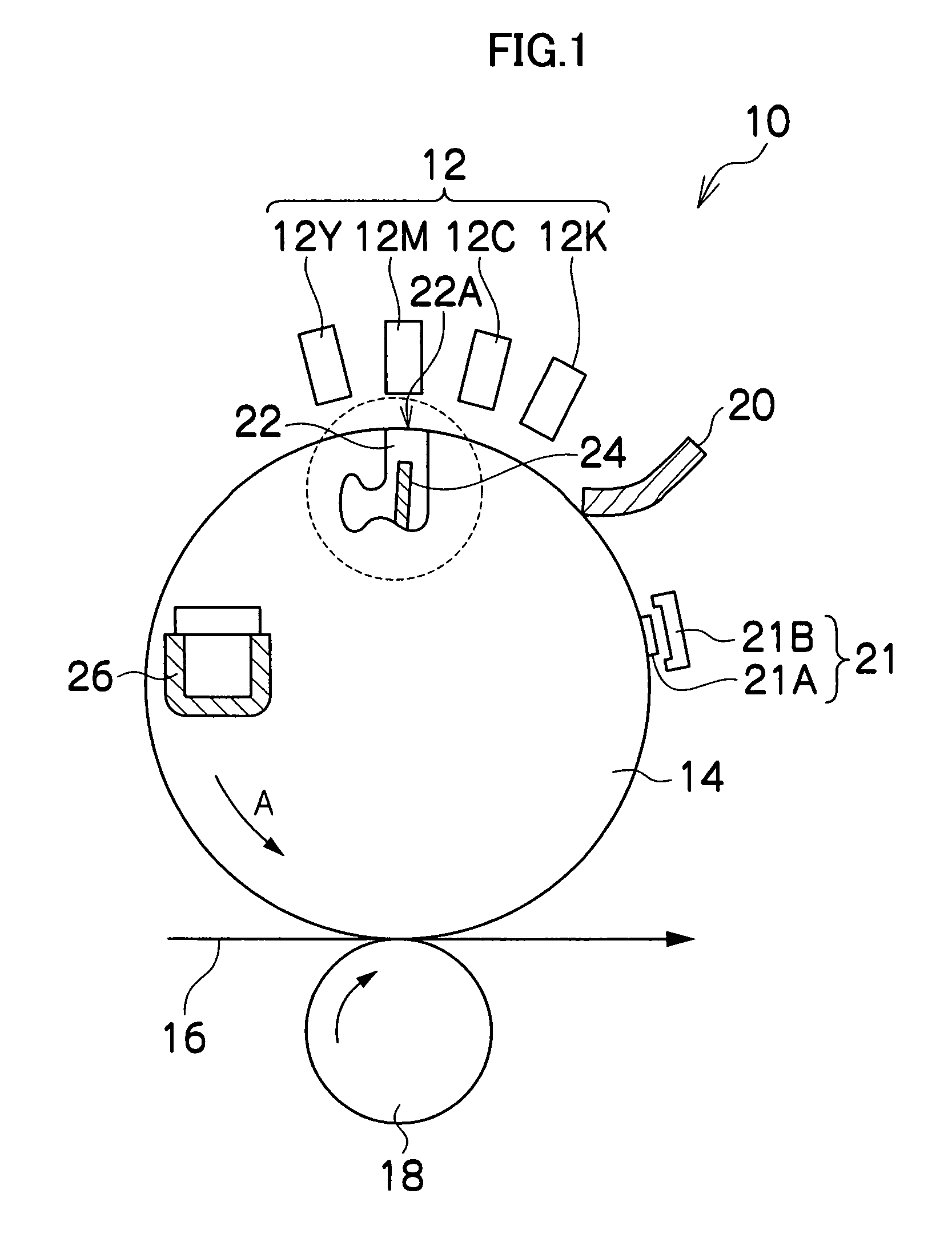
[0019]According to this aspect of the invention, by providing the restrictor plate in the straight section, it is possible to prevent the occurrence of leaks caused by the ink inside the first groove flowing back along the straight section.
[0022]According to this aspect of the invention, the ink inside the first groove is retained by the second groove and therefore it is possible to prevent leaks from the first groove.
[0025]According to this aspect of the invention, it is possible to make the first cleaning device contact the intermediate transfer body in a reliable fashion, by causing the first cleaning device to undergo elastic deformation in such a manner that the first cleaning device makes contact with the image forming surface of the intermediate transfer body. Moreover, by satisfying the relationship d0>d1 between the length d0 of the first groove in the direction of movement and the length d1 of the portion of the first cleaning device which makes contact with the intermediate transfer body, in the direction of movement, then it is possible for the first cleaning device to be restored from the elastic deformation and enter reliably into the first groove, and it is also possible to achieve reliable contact between the first cleaning device and the second cleaning device.
[0027]According to this aspect of the invention, by providing the first cleaning device in an oblique fashion with respect to the direction in which the first groove is formed (in other words, the direction in which the second cleaning device is provided), it is possible to make the second cleaning device come into contact with the first cleaning device successively, from one end toward the other end of the first cleaning device, and therefore the occurrence of any unwiped areas on the first cleaning device can be prevented.

Problems solved by technology

Furthermore, it may also happen that ink is left on the intermediate transfer body rather than being transferred to the recording medium, due to insufficient pressing force during transfer, or the like.
There is a possibility that the presence of residual ink of this kind may affect image quality, and therefore it is necessary to remove the residual ink from the intermediate transfer body before forming the next image.
However, in a method which wipes an intermediate transfer body by means of a blade, foreign matter accumulates on the blade and it becomes necessary to recover the foreign matter attached to the blade and to clean the blade, at periodic intervals.
The method described in Japanese Patent Application Publication No. 8-39828 is conceivable as a method of cleaning the blade, but Japanese Patent Application Publication No. 8-39828 makes no mention of a method for recovering foreign matter which has been removed from the blade, and there is a concern that foreign matter or ink accumulated on the plate member or in the gaps may fall onto the image, thereby degrading image quality.
In a method which wipes an intermediate transfer body by means of a web member, there is a possibility of increased costs since the web is a consumable item, and in a method which cleans the intermediate transfer body by means of a cleaning solution, it is necessary to recover the cleaning solution, and furthermore, the cleaning solution is also a consumable item.
In other words, a portion of the ink in the state of a meniscus formed between the removal roller and the transfer roller passes beyond the removal roller and remains on the transfer drum, and this may give rise to degradation of the image quality by mixing with subsequently ejected droplets of ink.

Method used


Image

  • Inkjet recording apparatus and cleaning method
  • Inkjet recording apparatus and cleaning method
  • Inkjet recording apparatus and cleaning method

Examples


modification example

[0182]Next, a modification example of the present embodiment is described below. The embodiment is described above with respect to a mode where only one groove 22 (and one second cleaning blade 24) is provided in the intermediate transfer drum 14, but it is also possible to provide a plurality of grooves. FIG. 21 shows a state where a groove 22′ is provided in the intermediate transfer drum 14 on the opposite side from the groove 22 (namely, in a rotationally symmetrical position rotated by 180° degrees about the center of rotation of the intermediate transfer drum 14). According to the mode shown in FIG. 21, in a two-liquid type of inkjet recording apparatus which uses a treatment liquid that cures the ink by reacting with the ink, for example, it is possible to prevent the ink from curing due to reaction between the ink and the treatment liquid inside the groove, by separating the groove which accommodates the ink from the groove which accommodates the treatment liquid.

[0183]Furth...


PUM


Abstract

An inkjet recording apparatus that includes an intermediate transfer body that has an image forming surface including an image forming region on which an image is formed by means of the ink droplets ejected from an ink ejection head and a cleaning device which makes contact with the image forming surface of the intermediate transfer body to wipe off and remove adhering material attached to the intermediate transfer body. A second cleaning device makes contact with the first cleaning device to remove adhering material attached to the first cleaning device. An ejection control device controls ink ejection from the head and a recovery device is provided which recovers the adhering material removed by the second cleaning device.

Description

BACKGROUND OF THE INVENTION[0001]1. Field of the Invention[0002]The present invention relates to an inkjet recording apparatus and a cleaning method, and more particularly, to a technology of cleaning an intermediate transfer body in an inkjet recording apparatus which uses the intermediate transfer body, whereby ink and foreign matter remaining on the intermediate transfer body are removed with reducing the cost of consumables or the like.[0003]2. Description of the Related Art[0004]There are inkjet recording apparatuses which use an intermediate transfer system in which an image is formed on an intermediate transfer body by means of ink ejected from a recording head, and then the image on the intermediate transfer body is transferred to a recording medium. In an intermediate transfer system, when printing a full face image in which an image is recorded onto the whole surface of the recording medium without leaving borders, the image is also formed to the outside of the region corr...

Claims


Application Information

Patent Timeline
Patent Type & Authority Patents(United States)
IPC IPC(8): B41J2/165
CPCB41J2/16585
Inventor KOJIMA, TOSHIYA
Owner FUJIFILM CORP
Why Eureka
Try Eureka