
Method and system for generating electrical energy within a vehicle tyre

Active Publication Date: 2008-08-26
PIRELLI TYRE SPA
View PDF17 Cites 35 Cited by
  • Summary
  • Abstract
  • Description
  • Claims
  • Application Information

AI Technical Summary

Benefits of technology

[0014]The Applicant has faced the problem of generating a sufficient power to be supplied to an electronic device, included within a tyre, adapted for monitoring at least one tyre parameter (e.g. pressure, temperature, number of tyre revolutions, traveled distance, rotational speed, acceleration), by mechanical-electrical energy conversion, exploiting piezoelectric effect. According to the Applicant, a structure of piezoelectric element suitable for obtaining this result should be of a cantilever-mounted flexure type, mounted in a portion of the tyre in correspondence of a tread area. However, another requirement for the piezoelectric element is durability. In other words, a structure comprising a cantilever-mounted flexure type piezoelectric element, mounted in a portion of a tyre in correspondence of a tread area, should also guarantee a resistance to early cracks and / or breakings that may be caused by the tremendous centrifugal force to which the piezoelectric element is subjected during rolling of the tyre, especially at high speed.
[0016]In other words, when the tyre rotates at low speed, a high quantity of electrical energy is generated by the oscillations of the piezoelectric element during a complete revolution of the tyre. The small gap and the rigidity of the piezoelectric element do not allow large deflections of the piezoelectric element, so that occurrence of cracks and / or breakings due to substantially continuous oscillation is reduced. When the tyre rotates at high speed, the high radial acceleration to which the piezoelectric element is subjected is counteracted by the contact with the inner walls of the housing for almost a complete revolution of the tyre, except during passage of the piezoelectric element in correspondence of the contact patch. This also reduces the occurrence of cracks and / or breakings in the piezoelectric material. However, energy is still generated due to substantially free oscillation of the piezoelectric element during the passage of the piezoelectric element in correspondence of the contact patch, where the radial acceleration is substantially null.
[0020]rotating said tyre on said roiling surface at a second rotation speed higher than said given speed, so as to cause said loading mass to contact said inner wall during a first fraction of a complete tyre revolution, during said first fraction said tread area corresponding to said tyre portion being not in contact with the rolling surface, and to cause said loading mass to oscillate within said gap during a second fraction of a complete tyre revolution, during said second fraction said tread area corresponding to said tyre portion being in contact with the rolling surface, thereby leading to a second deformation of said piezoelectric element during said tyre rotation;

Problems solved by technology

However, energy is still generated due to substantially free oscillation of the piezoelectric element during the passage of the piezoelectric element in correspondence of the contact patch, where the radial acceleration is substantially null.

Method used


Image

  • Method and system for generating electrical energy within a vehicle tyre
  • Method and system for generating electrical energy within a vehicle tyre
  • Method and system for generating electrical energy within a vehicle tyre

Examples


Embodiment Construction

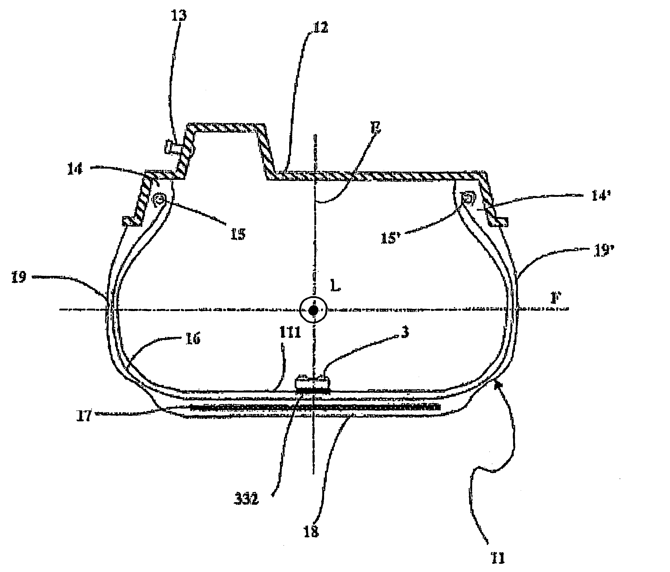
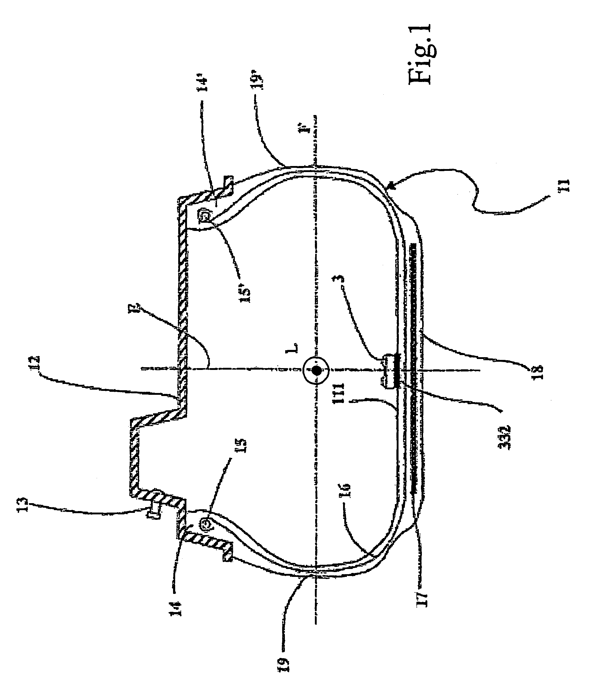
[0047]FIG. 1 shows a cross section of a wheel comprising a tyre 11 and a supporting rim 12. The tyre 11 shown in FIG. 1 is of a type conventionally known as “tubeless”, i.e. it does not include an inner tube. This tyre can be inflated by means of an inflation valve 13 positioned, for example, on the channel of the said rim 12.

[0048]The tyre 11 includes a carcass 16, terminating in two beads 14 and 14′, each formed along an inner circumferential edge of the carcass 16, for fixing the tyre 11 to the corresponding supporting rim 12. The beads 14, 14′ comprise respective reinforcing annular cores 15 and 15′, known as bead cores. The carcass 16 is formed by at least one reinforcing ply, including textile or metallic cords, extending axially from one bead 14 to the other 14′ in a toroidal profile, and having it ends associated with a respective bead core 15 and 15′. In tyres of the type known as radial, the aforesaid cords lie essentially in planes containing the axis of rotation of the t...


PUM


Abstract

A tire has a piezoelectric flexing element associated with an energy storage device (e.g., a capacitor). The piezoelectric flexure element is mounted in cantilever fashion in a housing so as to be positioned substantially along a plane orthogonal to a radial direction of the tire and, so that a first end of the piezoelement is restrained by the housing. A loading mass is coupled to the second end of the piezoelectric flexure element. A small gap is formed between the inner walls of the housing and the outer surface of the loading mass in order to allow limited flexure of the piezo-electric element. The housing including the piezoelectric is mounted in a tire portion in correspondence of a tread area of the tire, preferably on the inner surface of the tire. The piezoelectric element flexes under the action of the radial acceleration when the tire rotates. The loading mass and the gap are chosen to obtain a) small entity oscillations of the flexure element substantially during a complete revolution of the tire when the tire rotates at low speed; b) large entity oscillations of the flexure element substantially only during the passage of the tire portion including the piezoelectric element in the contact patch. Sufficient electrical power for powering an electronic device included within the tire is obtained, together with a long durability of the piezoelectric element.

Description

CROSS REFERENCE TO RELATED APPLICATION[0001]This application is a national phase application based on PCT / IB2003 / 006218, filed Dec. 29, 2003, the content of which is incorporated herein by reference.BACKGROUND OF THE INVENTION[0002]1. Field of the Invention[0003]The present invention relates to a method and system for generating electrical energy within a vehicle tyre. More specifically, electrical power is generated by using piezoelectric technology to convert mechanical strain, due to tyre flexure during rolling, to electric charge, that is stored in an energy storage device, and is thus made available to an electronic device disposed within the tyre. The present invention also relates to a system for monitoring operating parameters of a tyre.[0004]2. Description of the Related Art[0005]The incorporation of electronic devices within pneumatic tyres is taking a greater importance in order to increase safety of vehicles. Tyre electronics may include sensors and other components suit...

Claims


Application Information

Patent Timeline
IPC IPC(8): G01M17/02H02N2/18B60C23/04H01L41/113
CPCB60C23/0411H02N2/18H01L41/1136H10N30/306H02N2/00
Inventor MANCOSU, FEDERICORAMPANA, BARBARAMARIANI, FABIOCALATRONI, ANDREA
Owner PIRELLI TYRE SPA
Learn More