High frequency connector

a high-frequency connector and connector technology, applied in the direction of coupling device connection, printed circuit, two-part coupling device, etc., can solve the problem of balance impedance error, achieve the effect of facilitating space, effectively protecting from loosening, and simplifying the construction and manufacture of the connector

Active Publication Date: 2008-08-26
LIH YEU SENG IND
View PDF4 Cites 12 Cited by
  • Summary
  • Abstract
  • Description
  • Claims
  • Application Information

AI Technical Summary

Benefits of technology

[0007]It is another objective of the present invention to provide a high frequency connector, which is constructed by assembling a first module and a second module mutually. The second module comprises a connecting element having a through hole formed at one side thereof and can be locked with a connector by screwing. The connector has a relatively larger accommodating space for receiving an insulator and the insulator permits a needle to pass through. An effective end of the needle pierces through the connecting element and juts out of the connecting element into a relatively smaller through hole. Additionally, the needle has another end near the connector contacting an insulator. Further, a positioning element is locked with a fabricating hole by screwing. Moreover, a connector is fastened to the connecting element at one end where the needle protrudes. An outer end of the smaller through hole of the connecting element forms a chamfered section. The chamfered section permits an enlarged sectional area so that the air retained therein as well as the air retained in a vacant space of the through hole can function as insulation during signal transmission. Also, the chamfered section balances impedance errors that may be caused by different diameters of the needles of the first and second modules when the two modules are mutually engaged.
[0008]It is another objective of the present invention to provide a high frequency connector that is constructed by assembling a first module and a second module mutually. A C-shaped retaining ring is coupled with an annular groove of a connecting element of the second module and has an effective end outwardly warped for facilitating the combination between the connecting element and a connector. Thereby,

Problems solved by technology

Also, the chamfered section balances impedance errors that may be caused by different diamet

Method used


Image

  • High frequency connector
  • High frequency connector
  • High frequency connector

Examples


Embodiment Construction

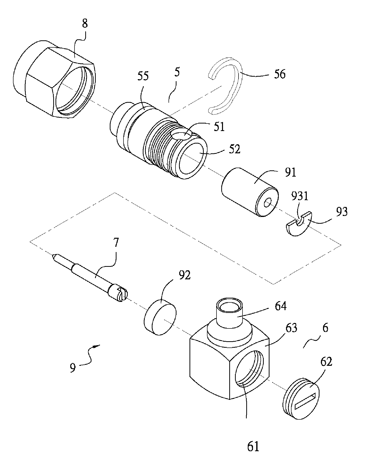
[0027]Referring to FIGS. 8 and 9, a high frequency connector of the present invention comprises a first module 4 and a second module 9.

[0028]The first module 4 (referring to FIGS. 4 and 5) comprises a connecting element 1 having a through hole 11 for receiving an insulator 41, and having a gap 12 formed at one side. By this gap 12, the mating length between the connecting element 1 and a connector 2 can be enhanced. An L-shaped needle 3 can be inserted into a through hole 411 of the insulator 41 while extending into a 90° angle to penetrate a horizontal segment 21 of the connector 2 so that a relative rotation between the connecting element 1 and the connector 2 is restricted. A positioning insulator 42 is settled between the connecting element 1 and the connector 2 at the bent portion of the L-shaped needle 3, while an insulator 43 is inserted into the horizontal segment 21. The positioning insulator 42 herein functions for eliminating impedance errors. The first module 4 construct...


PUM


Abstract

A high frequency connector includes a first module and a second module for signal transmission. The two modules are easily manufactured and assembled. The disclosed high frequency connector can maneuverably connect with the connector thereof according to the required direction of signal transmission so that competent transmissive connection is achieved when the two modules are assembled and thus preventing generation of noise. The volume of each of the two modules is precisely designed so that the high frequency connector facilitates reduction in power loss when being implemented for the purpose of signal transmission.

Description

BACKGROUND OF THE INVENTION[0001]1. Technical Field[0002]The present invention relates to high frequency connectors and, more particularly, to a high frequency connector comprising two modules that can be easily manufactured and promptly assembled. The two modules of the disclosed high frequency connector can maneuverably connect with each other according to a required direction of signal transmission, so that a competent transmissive connection can be achieved when the two modules are assembled, and thus preventing generation of noise. The volume of each of the modules is precisely designed so that the high frequency connector facilitates reduction in power loss when being implemented for the purpose of signal transmission.[0003]2. Description of Related Art[0004]A presently developed high frequency connector for the purpose of signal transmission is typically constructed by assembling a first module 10 and a second module 20 (referring to FIGS. 1 through 3). The first module 10 (r...

Claims


Application Information

Patent Timeline
IPC IPC(8): H01R12/00
CPCH01R24/44H01R2103/00
Inventor HSU, CHIN-TENG
Owner LIH YEU SENG IND
Why Eureka
Try Eureka