Warming device for fuel cell system

Inactive Publication Date: 2008-08-26
TOYOTA IND CORP
View PDF6 Cites 1 Cited by
  • Summary
  • Abstract
  • Description
  • Claims
  • Application Information

AI Technical Summary

Benefits of technology

[0012]An object of the invention is to provide a warming device for a fuel cell system capable of reducing warming time of the fuel cell system as compared with the case where an electric heater is energized with a temperature of a storage battery (secondary battery) kept low in warming to heat a fuel battery.

Problems solved by technology

However, if the temperature is low (for example, 0° C. or less) at the start of the power generation, power cannot be generated or is inefficiently generated.
However, generated water sometimes remains in a gas passage when the fuel battery is stopped.
At a low temperature, moisture in an electrolyte membrane of the polymer electrolyte fuel cell may freeze, which may prevent power generation or significantly reduce power generation efficiency.
Even at a temperature that causes no freeze of water, the polymer electrolyte fuel cell generally generates power at the preset temperature, and thus requires quick warming on a cold day.
However, a secondary battery incorporated in a fuel cell vehicle produces high output at a normal temperature (a temperature that requires no warming), but remains producing low output at a low temperature that requires warming.
Therefore, if the method described in Japanese Laid-Open Patent Publication No. 63-91967 is applied to warming of a fuel cell vehicle, the heater is energized in a low output state of the secondary battery to warm the fuel battery and the secondary battery, which takes much time.

Method used


Image

  • Warming device for fuel cell system
  • Warming device for fuel cell system
  • Warming device for fuel cell system

Examples


first embodiment

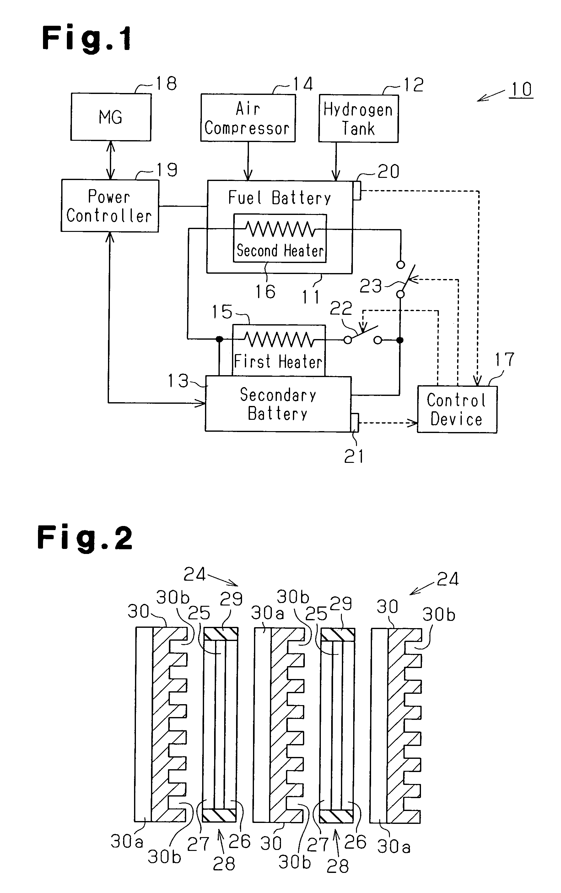
[0026]A fuel cell vehicle according to the present invention will now be described with reference to FIGS. 1 to 4.

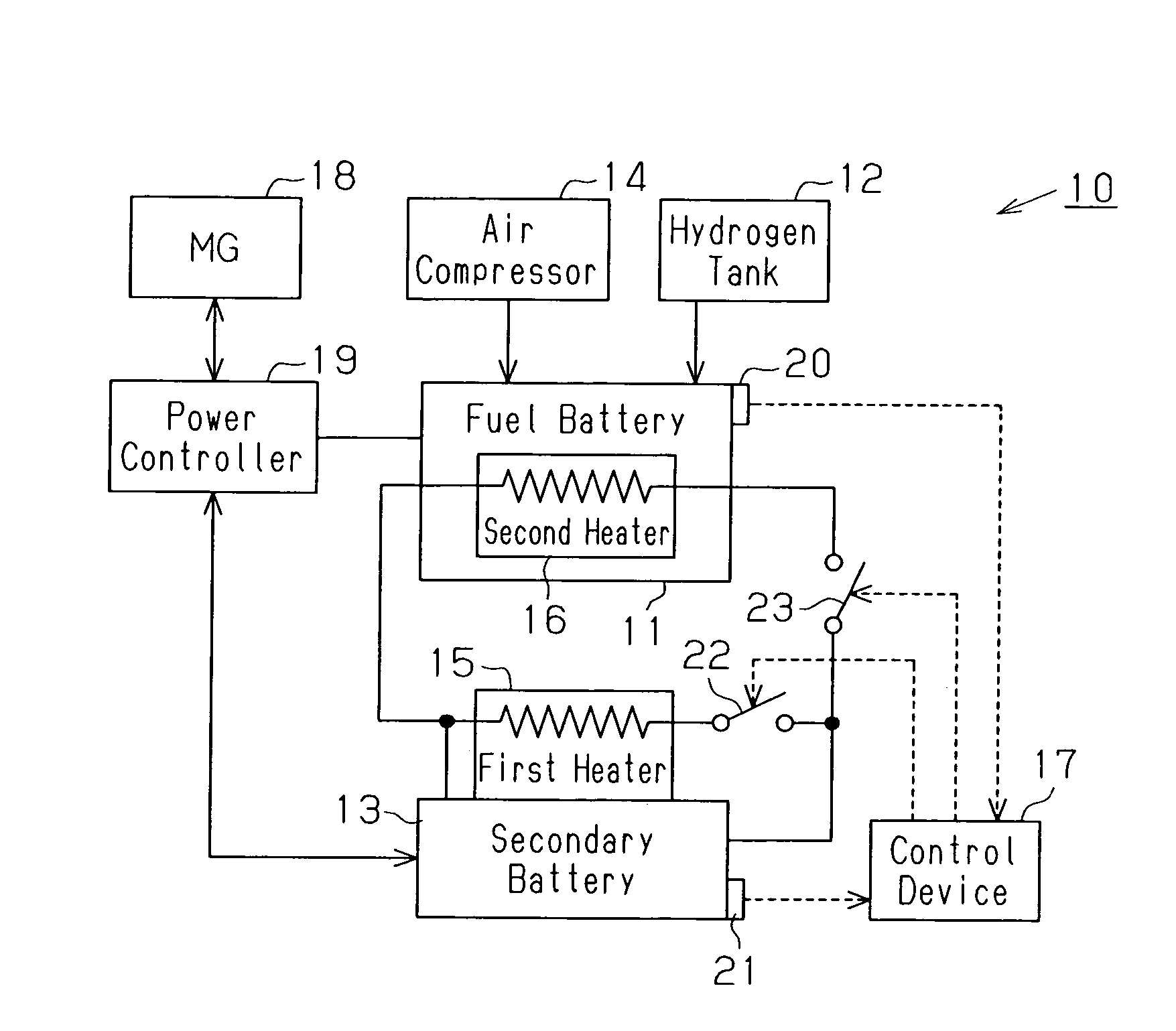
[0027]As shown in FIG. 1, a fuel cell system 10 includes a fuel battery 11, a hydrogen tank 12 as a hydrogen source, a secondary battery 13 as a power storage device, an air compressor 14 as an oxygen supply source, a first heater 15 as a first heating device, a second heater 16 as a second heating device, and a control device 17. The fuel cell system 10 includes a motor generator 18 and a power controller 19 that drive wheels (not shown) of the fuel cell vehicle.

[0028]The fuel battery 11 is, for example, of a polymer electrolyte type, and generates electric energy (DC power) by a reaction of hydrogen supplied from the hydrogen tank 12 with oxygen supplied from the air compressor 14. The hydrogen tank 12 stores hydrogen at a high pressure, for example, of about 35 Mpa, depressurizes the hydrogen therein, and then supplies the hydrogen to the fuel battery 11 at a constant...

second embodiment

[0060]Next, the invention will be described with reference to FIG. 5. This embodiment is different from the embodiment in FIGS. 1 to 4 in that only a part of a fuel battery 11 can generate power, a second heater 16 can heat only the part of the fuel battery 11, and when the part of the fuel battery 11 reaches a temperature that allows power generation, power generation of the part of the fuel battery 11 is started.

[0061]As shown in FIG. 5, the fuel battery 11 is divided into two cell units 31a and 31b. The cell units 31a and 31b are independent from each other. A fuel cell vehicle requires some hundreds of fuel cells 24 electrically connected in series as a fuel battery 11 for generating required power. However, if the fuel battery 11 is constituted by a stack with some hundreds of fuel cells 24 connected linearly, the fuel battery 11 becomes long to make it difficult to ensure a space for the fuel battery 11. Thus, the fuel battery 11 is constituted by the two cell units 31a and 31...


PUM


Abstract

A warming device for fuel cell system having a fuel battery and a secondary battery has a first heater, a second heater and a control device. The first heater heats the secondary battery. The second heater heats the fuel battery by using electricity of the secondary battery. In warming of the fuel cell system, the control device first drives the first heater to heat the secondary battery to a preset temperature, and then drives the second heater. This reduces warming time of the fuel cell system.

Description

BACKGROUND OF THE INVENTION[0001]The present invention relates to a warming device for a fuel cell system having a fuel battery and a power storage device.[0002]In recent years, attention is being given to fuel cells, which are clean and provide high energy efficiency, as power sources for electric vehicles. A fuel battery produces an electromotive force by a chemical reaction of oxygen with hydrogen. Oxygen is supplied to a cathode, and hydrogen is supplied to an anode, and chemical energy obtained by the reaction of oxygen with hydrogen is directly converted into electric energy, thus providing high conversion efficiency.[0003]For use in a fuel cell vehicle, a compact fuel battery with high output is required, and a polymer electrolyte fuel cell (PEFC) is preferably used. The polymer electrolyte fuel cell efficiently generates electric power at a preset temperature (about 80° C.). Since a reaction that produces heat occurs in the fuel battery, efficient power generation can be con...

Claims


Application Information

Patent Timeline
IPC IPC(8): H01M8/04H01M8/10H01M8/00H01M16/00
CPCH01M8/04007H01M8/04268H01M16/006Y02T90/32H01M2250/20Y02E60/50H01M10/615H01M10/6571Y02T90/40Y02E60/10
Inventor ISOGAI, YOSHIHIRO
Owner TOYOTA IND CORP
Why Eureka
Try Eureka