Motorcycle

a technology for motorcycles and pivot plates, applied in the direction of crankshaft transmission, jet propulsion mounting, bicycle equipment, etc., can solve the problems of reducing the weight of the motorcycle and the strength of the pivot plate can be increased in the vicinity of the drive shaft. , the effect of facilitating the handling of tools

Inactive Publication Date: 2008-09-02
HONDA MOTOR CO LTD
View PDF11 Cites 21 Cited by
  • Summary
  • Abstract
  • Description
  • Claims
  • Application Information

AI Technical Summary

Benefits of technology

[0009]According to the pivot plates of present invention, the pivot plate on the drive shaft side is arranged closer to the vehicle body center side than the drive shaft and, at the same time, the portion of the pivot plate in the vicinity of the drive shaft is flattened and hence, a load from the swing arm is applied to the flattened portions whereby a force which bends the flattened portion is not generated at the flattened portion and the load is uniformly applied to the flattened portion. Accordingly, it is possible to obtain an advantage that the strength of the pivot plate in the vicinity of the drive shaft can be increased.
[0010]Further, since the pivot plate on the drive shaft side is arranged closer to the vehicle body center side than the drive shaft and the portion of the pivot plate in the vicinity of the drive shaft is flattened, in connecting the swing arm to the pivot plates on the drive shaft side using the bolt, the bolt can be easily inserted and the handling of a tool is facilitated thus enhancing the operability of the assembling.
[0012]Further, the pivot plate arranged closer to the drive shaft side than the lower pipe is offset to the vehicle body center side by extending the cross pipe between the left and right pivot plates in a state that the cross pipe projects from the pivot plates on the drive shaft side and by connecting the rear end of the lower pipe of the vehicle body frame to the projecting portion of the cross pipe. Accordingly, it is unnecessary to offset the lower pipe to the vehicle body center side along with the offsetting of the drive-shaft-side pivot plate and hence, it is possible to set a wide distance between the left and right lower pipes. As a result, it is possible to increase the degree of freedom in designing parts such as an oil pan positioned in the vicinity of the lower pipes.
[0013]With respect to the swing arm of present invention, the swing arm is fastened using one bolt which penetrates the left and right pivot plates and hence, a shape (an area) of a connecting portion which transmits a load applied to the swing arm to the bolt can be increased and, at the same time, the shape becomes one tubular shape. As a result, a force (a stress) transmitted to the connecting portion can be decreased. Accordingly, it is possible to increase the strength of the swing arm and, at the same time, it is possible to increase the strength of the fastening structure which fastens the swing arm (including the left and right pivot plates).

Problems solved by technology

However, in the rear arm bearing structure of the motorcycle described above, the pair of left and right brackets (pivot plates) have U-shaped bent portions, wherein when a force which bends the bent portions is increased and, the irregularities of the force applied to the bent portions are also increased depending on parts of the bent portions and hence, it is difficult to increase the strength of pivot plates while reducing the weight of the motorcycle.

Method used


Image

  • Motorcycle
  • Motorcycle
  • Motorcycle

Examples


Embodiment Construction

[0022]A best mode for carrying out the present invention is explained hereinafter in conjunction with attached drawings. Here, the drawings are observed in the direction of symbols. Terms “front”, “rear”, “left”, “right”, “upper” and “lower” indicate directions as viewed from a rider.

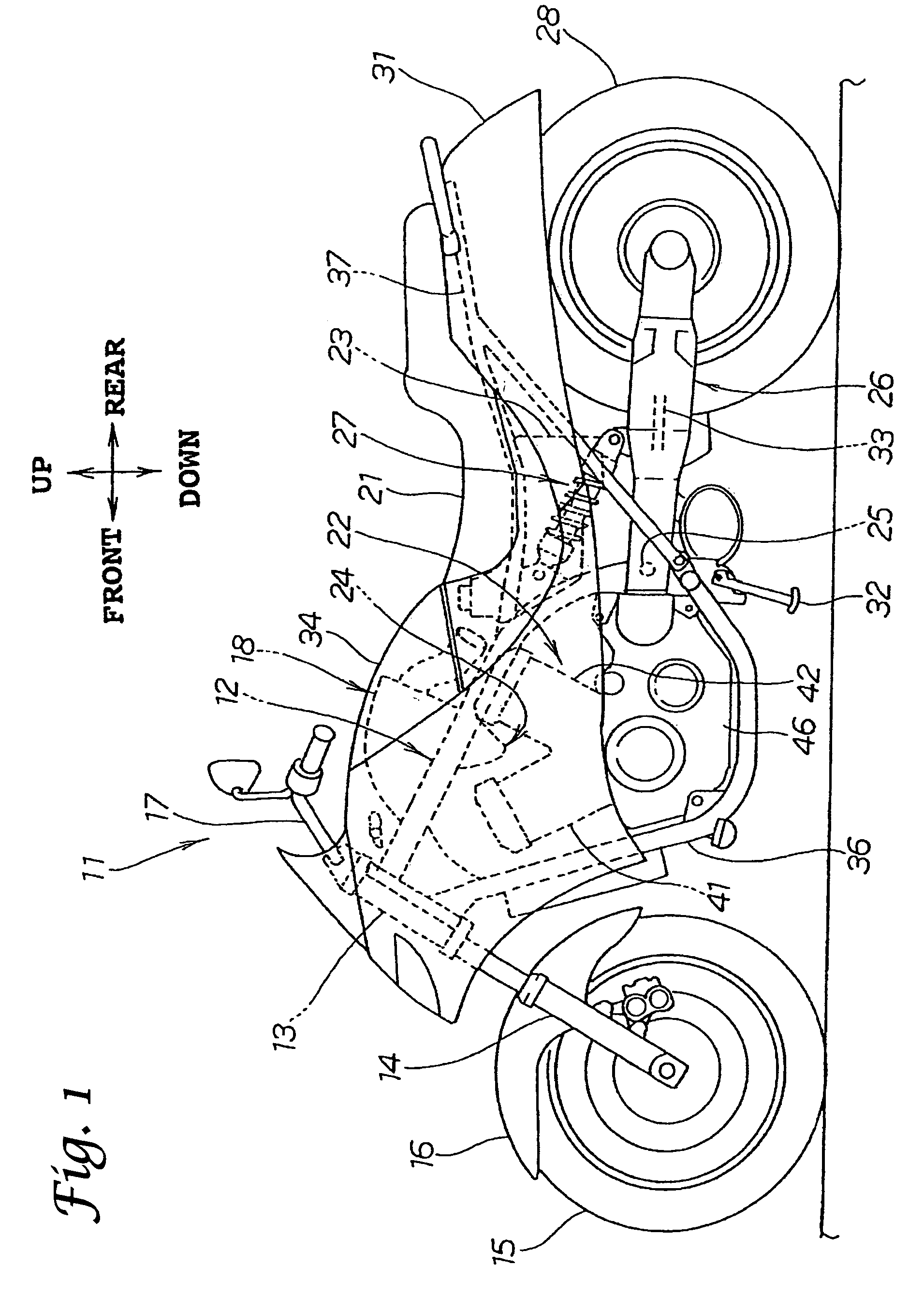
[0023]FIG. 1 is a side view of a motorcycle according to the present invention.

[0024]The motorcycle 11 includes a vehicle body frame 12, a front fork 14 which is mounted on a head pipe 13 of the vehicle body frame 12, a front wheel 15 and a front fender 16 which are mounted on the front fork 14, a handle 17 which is connected to the front fork 14, an air cleaner 18 which is arranged on a front upper portion of the vehicle body frame 12, a seat 21 which is mounted on an upper portion of the vehicle body frame 12, a V-type engine 22 which is arranged at the center of the vehicle body frame 12, a fuel tank 23 which is arranged behind the V-type engine 22 and below the seat 21, a carburetor 24 which is conn...


PUM


Abstract

In a motorcycle, a pivot plate on a drive shaft side is arranged closer to a vehicle body center axis side than the drive shaft and, at the same time, a swing arm mounting portion of the pivot plate in the vicinity of the drive shaft is flattened. Further, a lower cross pipe is extended between the left and right pivot plates in a state that the lower cross pipe projects from the pivot plate on the drive shaft side, a down tube is lowered from a head pipe, a lower pipe is extended rearwardly in the longitudinal direction of a vehicle body frame from a lower end of the down tube, and a rear end of the lower pipe is connected to a projecting portion of the lower cross pipe thus offsetting the pivot plate arranged closer to the drive shaft side than the lower pipe to the vehicle body center axis side.

Description

FIELD OF THE INVENTION[0001]The present invention relates to a motorcycle which includes a drive shaft for driving a rear wheel and a vehicle body frame which corresponds to the drive shaft.BACKGROUND OF THE INVENTION[0002]There has been known a motorcycle having a vehicle body frame which conforms to a shaft drive method. For example, see Japanese Accepted Patent Publication Sho63 (1988)-35477 (page 6, FIG. 4)[0003]According to the figure, the conventional rear arm bearing structure of the motorcycle is constituted of a structure in which a propeller shaft is accommodated in a rear arm, and the rear arm is mounted on a pair of left and right brackets (including bearing pipes) which are integrally formed on the main frame.[0004]However, in the rear arm bearing structure of the motorcycle described above, the pair of left and right brackets (pivot plates) have U-shaped bent portions, wherein when a force which bends the bent portions is increased and, the irregularities of the force ...

Claims


Application Information

Patent Timeline
Patent Type & Authority Patents(United States)
IPC IPC(8): B60K8/00B62K19/30
CPCB62M17/00B62K25/283B62K11/04B62K19/20
Inventor YAMAKURA, YUTAKASHIBUKAWA, TAKERO
Owner HONDA MOTOR CO LTD
Why Eureka
Try Eureka