Canting vertical fore grip with bipod

a vertical fore grip and bipod technology, applied in the field of cantering devices, can solve the problems of not revealing the fore grip or gun handle of a concealable and collapsible bipod, the placement of the tripod legs on the exterior of the handle, and the severe restriction of the deployment and storage of the tripod legs

Inactive Publication Date: 2008-09-09
GRIP POD SYST INT
View PDF57 Cites 72 Cited by
  • Summary
  • Abstract
  • Description
  • Claims
  • Application Information

AI Technical Summary

Benefits of technology

[0020]Another canting member can include an upper mount member for allowing the firearm to cant relative to the legs on which the firearm is supported. The upper mount member can include an upper clamp for claming the upper mount member to a firearm mounting rail, and a lower clamp for clamping the upper mount member to an upper portion of the fore grip. The upper mount member can include a tilt rail that is clamped by the upper por

Problems solved by technology

These patents disclose the respective art in relation to bipods, but do not disclose a fore grip or gun handle with a concealable and collapsible bipod.
An examination of this patent reveals a number of problems with this device, and the most obvious problem is that the tripod legs are positioned on the exterior of the handle when not deployed.
If the gun with this device attached was being used in wet or muddy environments, either in a deployed or storage position, the ingress of mud and dirt into and around the handle could result in the deployment and storage of the tripod legs being severely restricted due to the mud or foreign matter.
Another problem is that deployment requires the rotation of a disengagement cam to

Method used


Image

  • Canting vertical fore grip with bipod
  • Canting vertical fore grip with bipod
  • Canting vertical fore grip with bipod

Examples


Embodiment Construction

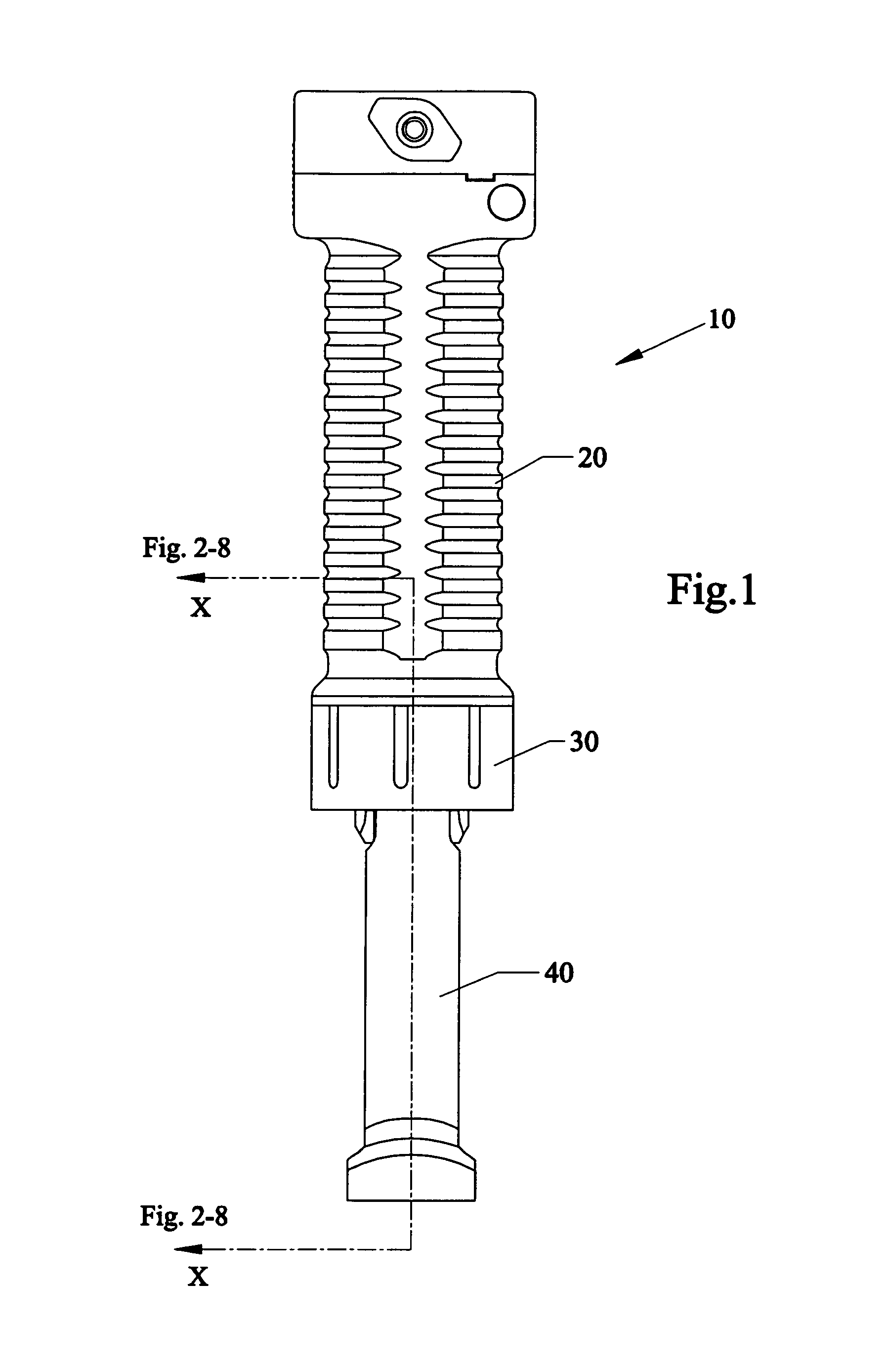
[0060]Before explaining the disclosed embodiment of the present invention in detail, it is to be understood that the invention is not limited in its application to the details of the particular arrangement shown since the invention is capable of other embodiments. Also, the terminology used herein is for the purpose of description and not of limitation.

[0061]The invention is a continuation in part of U.S. patent application Ser. No. 11 / 485,762 filed Jul. 13, 2006, which is a Continuation-In-Part of U.S. patent application Ser. No. 10 / 725,082 filed Dec. 2, 2003, now U.S. Pat. No. 7,111,424, and is a Continuation-In-Part of U.S. Design patent application Ser. No. 29 / 267,729 filed Oct. 20, 2006 which is a divisional of U.S. Design patent application 29 / 259,347 filed May 5, 2006, all of which are incorporated by reference.

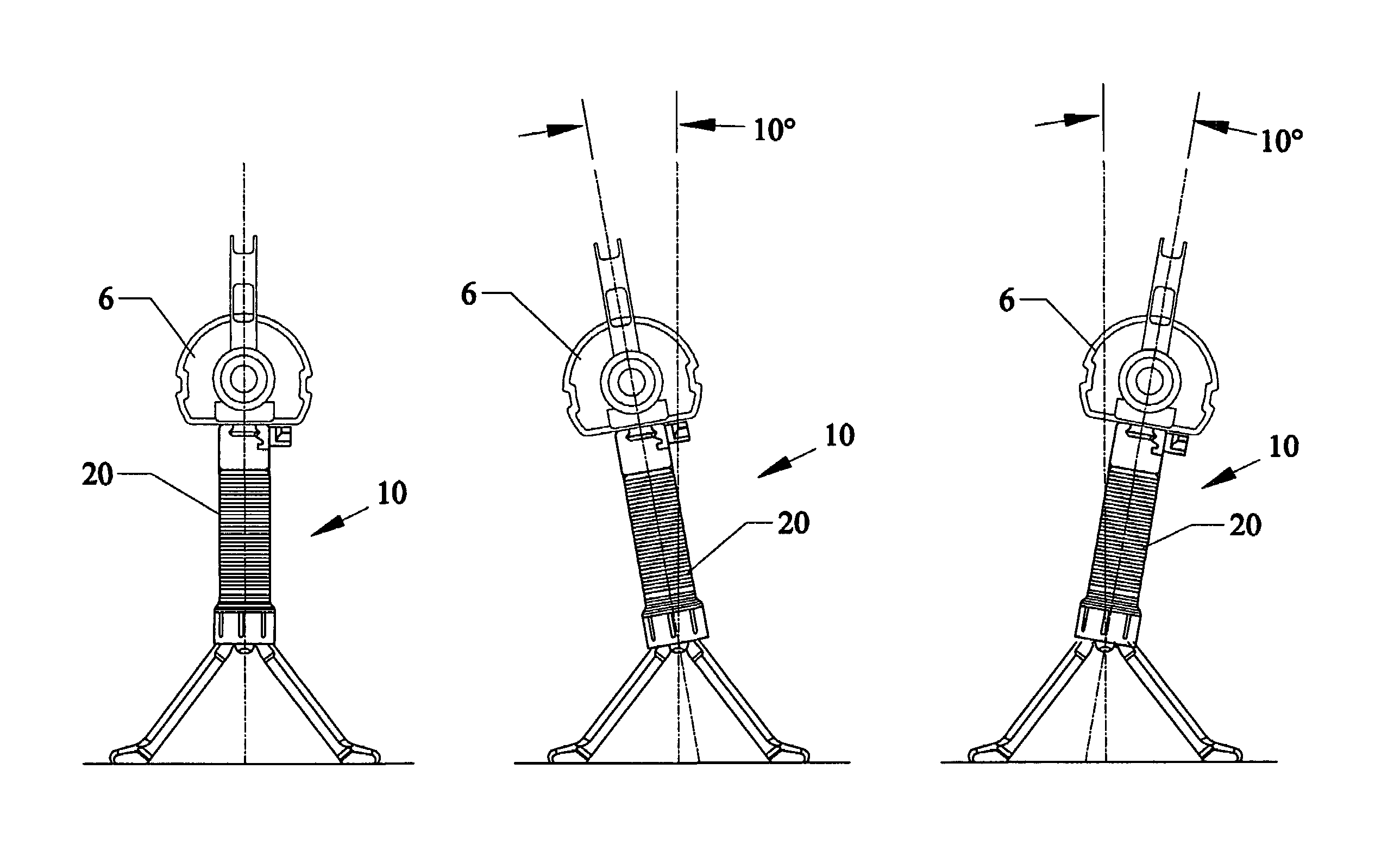
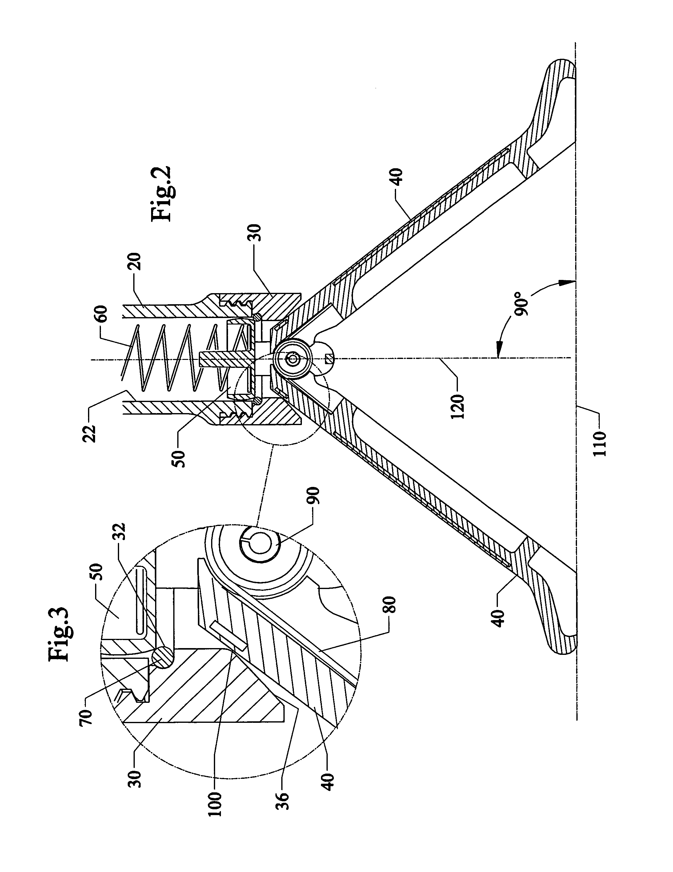
[0062]The invention can use the fore grips that were described and shown in reference to the parent and copending inventions. For example, a plurality of legs can be c...


PUM


Abstract

Devices, systems and methods of canting firearms such as rifles relative to fore grip having extendable and expanded legs. One version allows for a rocking and canting of the firearm by pivotally attaching an upper portion of the expanded legs. Another version allows for a separate canting member to be clamped to both the upper portion of a vertical fore grip and to the lower mounting rail of the firearm. The canting member has portions that cant (move to the left or to the right) relative to one another. An operator can cant the firearm in a free-state or to fixed positions as desired.

Description

[0001]This invention is a continuation in part of U.S. patent application Ser. No. 11 / 485,762 filed Jul. 13, 2006, which is a Continuation-In-Part of U.S. patent application Ser. No. 10 / 725,082 filed Dec. 2, 2003, now U.S. Pat. No. 7,111,424, and is a Continuation-In-Part of U.S. Design patent application Ser. No. 29 / 267,729 filed Oct. 20, 2006 now U.S. Pat. No. D,566,220 which is a divisional of U.S. Design patent application 29 / 259,347 filed May 5, 2006 U.S. Pat. No. D,566,219.FIELD OF THE INVENTION[0002]The present invention relates to guns and more particularly to cantering devices, apparatus, systems and methods of allowing a firearm to cant (move to the left and the right) relative to a support stand such as a fore grip / gun handle with a pistol grip having a concealable and collapsible bipod.BACKGROUND AND PRIOR ART[0003]Over the years, there has been considerable prior art for bipod devices, that date back to pre-20th century times, with bipods having a familiar appearance, s...

Claims


Application Information

Patent Timeline
IPC IPC(8): F41C23/00
CPCF41C23/16F41A23/08
Inventor MOODY, JOSEPH R.GADDINI, JOSEPH D.
Owner GRIP POD SYST INT
Why Eureka
Try Eureka